


6
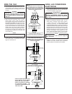
FIG. 12
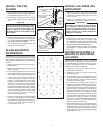
FIG. 14
INSTALL THE FAN
BLADES
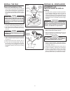
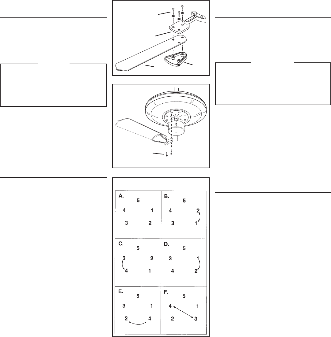
1. Fasten blades to blade brackets. Make sure
that blade mounting screws are tightened firmly
into blade bottom backets. (FIG. 12)
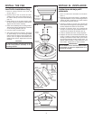
2. Fasten blade brackets to fan motor. Tighten
blade bracket mounting screws firmly. (FIG.
13)
CAUTION
The blades and blade brackets have been
carefully balanced to prevent wobble when
the fan is operating. Handle blades and
brackets carefully to avoid bending them.
Bent blade brackets are the primary cause
of fan wobble.
3. Install optional light kit at this time. Follow the
instructions packed with the kit. USE ONLY A
U.L. LISTED LIGHT KIT MARKED FOR USE
WITH THIS CEILING FAN MODEL.
4. Turn on power and check operation of fan and
light kit, if fan is so equipped.
BLADE BALANCING
INFORMATION
All blades are grouped by weight. Natural woods
vary in density, which could cause the fan to wobble
slightly, even though all blades are weight-matched.
The procedures listed below should eliminate any
wobble.
1. Make sure that all blades are screwed firmly to
blade brackets.
2. Make sure that all blade brackets are screwed
firmly to fan motor.
3. If fan is equipped with light kit, make sure that
fitter is screwed firmly into switch box cover.
Center shade in fitter by adjusting thumbscrews.
4. If the previous steps do not eliminate the
wobble, the problem is possibly a bent blade
bracket or a warped blade. This can be deter-
mined by viewing each blade at its outer edge
with the fan running. A blade out of alignment
will be easy to see - there will be differences in
height at the blade tips while the fan is running.
Remember that stopping the blades suddenly
with your hand will probably bend the blade
bracket. A bent blade bracket or a warped blade
must be replaced. Contact your Broan
representitive for replacement.
5. If the previous step does not reveal a bent blade
bracket or a warped blade, it may be possible
to eliminate any wobble by interchanging the
blade/blade bracket assemblies as shown. Fol-
low the order shown and check for wobble af-
ter each switch. (FIG. 14)
INSTALE LAS ASPAS DEL
VENTILADOR
1. Asegure las aspas a sus soportes. Asegúrese
que los tornillos de montaje de las aspas estén
firmemente apretados dentro de los soportes
fondos. (FIG.12)
2. Asegure los soportes al motor del ventilador.
Apriete bien los tornillos de montaje. (FIG. 13)
PRECAUCION
Las aspas y los soportes se han equilibrado
con cuidado para evitar el bamboleo cuando
funciona el ventilador. Maneje las aspas y
soportes cuidadosamente para no torcerlos.
Soportes torcidos son la causa principal del
bamboleo del ventilador.
3. Instale ahora el juego de luces opcionales. Siga
las instrucciones que vienen con el juego. USE
SOLAMENTE UN JUEGO DE LUCES DE LISTA
U.L. INDICADO PARA USARSE CON ESTE
MODELO DE VENTILADOR DE TECHO.
4. Conecte la electricidad y chequee el funcionamiento
del ventilador y el juego de luces si el ventilador
lleva luces.
INFORMACION SOBRE LA
MANERA DE EQUILIBRAR
LAS ASPAS
Todas las aspas se agrupan por peso. Las maderas
naturales varían en densidad, lo cual puede hacer que
el ventilador bambolee ligeramente pese a que todas
las aspas concuerdan en peso. El procedimiento
indicado abajo eliminará el bamboleo.
1. Asegúrese que todas las aspas estén bien
atornilladas a los soportes.
2. Asegúrese que todos los soportes estén bien
atornillados al motor.
3. Si el ventilador lleva luces asegúrese que el
adaptador esté firmemente atornillado a la tapa de
la caja del interruptor. Centre la pantalla ajustando
los tornillos de apriete manual.
4. Si el procedimiento indicado arriba no elimina el
bamboleo, el problema posiblemente se debe a un
soporte de aspa torcido o a una aspa deformada.
Esto puede determinarse mirando el borde exterior
de cada aspa con el ventilador en funcionamiento.
Una aspa desalineada se ve fácilmente - se notará
diferencias en la altura en las puntas de la aspa
mientras funciona el ventilador. Recuerde Ud. que
si para las aspas repentinamente con la mano ello
probablemente torcerá el soporte. Un soporte
torcido o una aspa alabeada deben reemplazarse.
Póngase en contacto con el Representante de
Broan con respecto al reemplazo.
5. Si el procedimiento anterior no descubre un soporte
torcido o una aspa alabeada es posible eliminar el
alabeo intercambiando la posición de los conjuntos
de aspa/aspa soporte como se muestra. Siga el
orden indicado y vea si hay alabeo después de cada
intercambio. (FIG. 14)
FIG. 13
BLADE MOUNTING
SCREWS
TORNILLOS PARA MONTAR
LA ASPA
BLADE
BOTTOM
BRACKET
SOPORTE
DE LA
ASPA
FONDO
BLADE
ASPA
BLADE TOP BRACKET
SOPORTE DE LA
ASPA SUPERIOR
BLADE BRACKET
MOUNTING SCREWS
TORNILLOS PARA
ASEGURAR LOS
SOPORTES A LAS ASPAS