


1660-IN-010-0-04 Page 7
2.4 Adding Hardware
Observe proper ESD precautions (use an appropriately grounded wrist strap or
similar device) when installing any device.
2.4.1 Adding Boards
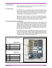
The OPtima PC has 1 PCI expansion slot and two ISA slots. Access to these
slots is through a cover (at the top of the DSA2; the side of the DSB2). Half-size
ISA cards will fit the ISA slots. Full size ISA cards will not. Cards longer than 7-
1/4” (185mm) will not fit in the ISA slots. PCI cards must be the standard 4-3/4”
(120mm) length. PCI Cards longer than this will not fit.
Card options that should function in the OPtima PC include PCI/ISA network
(ethernet, etc.), modem, and serial cards. PCI serial cards that autodetect ad-
dressing may work best. It is not recommended to use sound cards in the OPtima
PC (the voltages required for sound cards are not presently available).
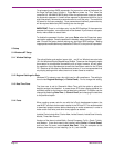
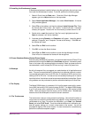
2.4.2 Installing the Modbus Plus SA85 Board
1. Set the memory address to D0000 (switch 2 in the “up” position; all others in the
“down” position). Place the jumper in the IRQ5 position. Set the Modbus Plus
address switches to Address 61 (which is reserved for the OPtima PC). Other
operator stations can be Address 62-64. Note that the address will be one higher
than the binary value set on the switches, so that Address 61 is entered as “001111”
(60). With the PC off, place the board in the ISA slot closest to the back. Screw
down the board and replace the cover.
If a 2nd SA85 card is added, the IRQ and memory address must be different from
the first card (set the memory address to D0800 or D4000 and check your system
config for an unused IRQ). Units with 2nd cards shipped BEFORE March 2001
were setup as IRQ7, memory address D4000. AFTER March 2001, units with
2nd cards were setup as IRQ2, memory address 0800.
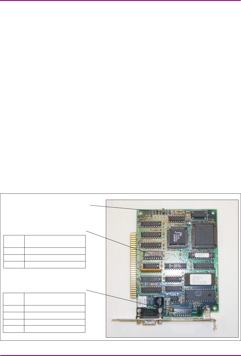
Figure 5. SA85 Board Jumpers & Switches
Jumper (shown in IRQ5 position)
Modbus Plus
Address Switches
Memory Base
Address Switches
Memory
Address
D0000
D0800
D4000
Switch Position (“down” = 0)
1
0
0
0
2
1
1
1
3
0
0
0
4
0
0
1
5
0
0
0
6
0
0
0
7
0
1
0
Switch 8 is not used.
Node
Address
61
62
63
64
Switch Position (“down” = 0)
1
0
1
0
1
2
0
0
1
1
3
1
1
1
1
4
1
1
1
1
5
1
1
1
1
6
1
1
1
1
Switch 7 and 8 are not used.