10
INSTALLATION (RETROFIT)
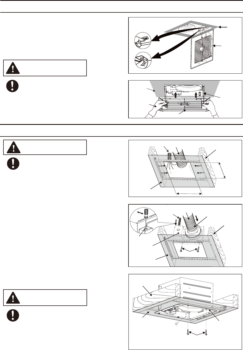
INSTALLATION (NEW CONSTRUCTION) CONTINUED
CAUTION
Fig.10
Fig.11
Grille
Grille
Ceiling
Mounting
spring
14. Insert the other mounting spring into the slot as
shown and mount grille to fan body. (Fig.11)
Mount grille carefully so that lead wire is
not pinched.
Ceiling
Gloves
13. Adjust Pick-A-Flow switch; if used, adjust the
FV-VS15VK1 Multi-Speed module. (Fig.10)
Refer to indication on page 6.
Ceiling
Flange
Joist
Machine screw (M4X6)
2 Self-drilling screws (Fix the
TM
flange and Flex-Z Fast bracket through the ceiling)
Fig.13
Mastic or
approved
foil tape
2 Self-drilling screws
Ceiling
Joist
Knock-out
hole
Junction box
cover
Conduit
Circular duct
Fig.14
Fig.12
10 7/8
(275)
10 7/8
(275)
Ceiling (already existed)
Conduit
Circular duct
4 Tapping
screws (ST4.2x20)
WARNING
1. Remove the existing fan and cut ceiling openning.
2. Follow the step 1, 4, 5 on page 8 and step 7 on
page 9. (Before connect the circular duct to the
adaptor, should pull down the circular duct from
the ceiling)
Disconnect power source before working
on unit.
5. Follow the step 10 to 14 on page 9 to 10.
TM
Secure the Flex-Z Fast bracket to joists by using 4
tapping screws (ST4.2x20)
.
Existing ductwork and wiring left in place. (Fig.12)
(Please prepare the
TM
screws and put on Flex-Z Fast bracket before
TM
Flex-Z Fast bracket is installed on joist)
TM
3. Install the adaptor to Flex-Z Fast bracket by
using 2 self-drilling screws. (Fig.13)
TM
4. Secure the fan body to Flex-Z Fast bracket by
using 2 self-drilling screws, plug connector to
receptacle and secure the fan body to adaptor
by using machine screw (M4X6). (Fig.14)
Secure machine screw (M4X6) to
TM
hole and not touch the Flex-Z Fast bracket.
Please fix the screw carefully to avoid screw
slip teeth.
the suitable
CAUTION
Joist
Unit: inches (mm)


