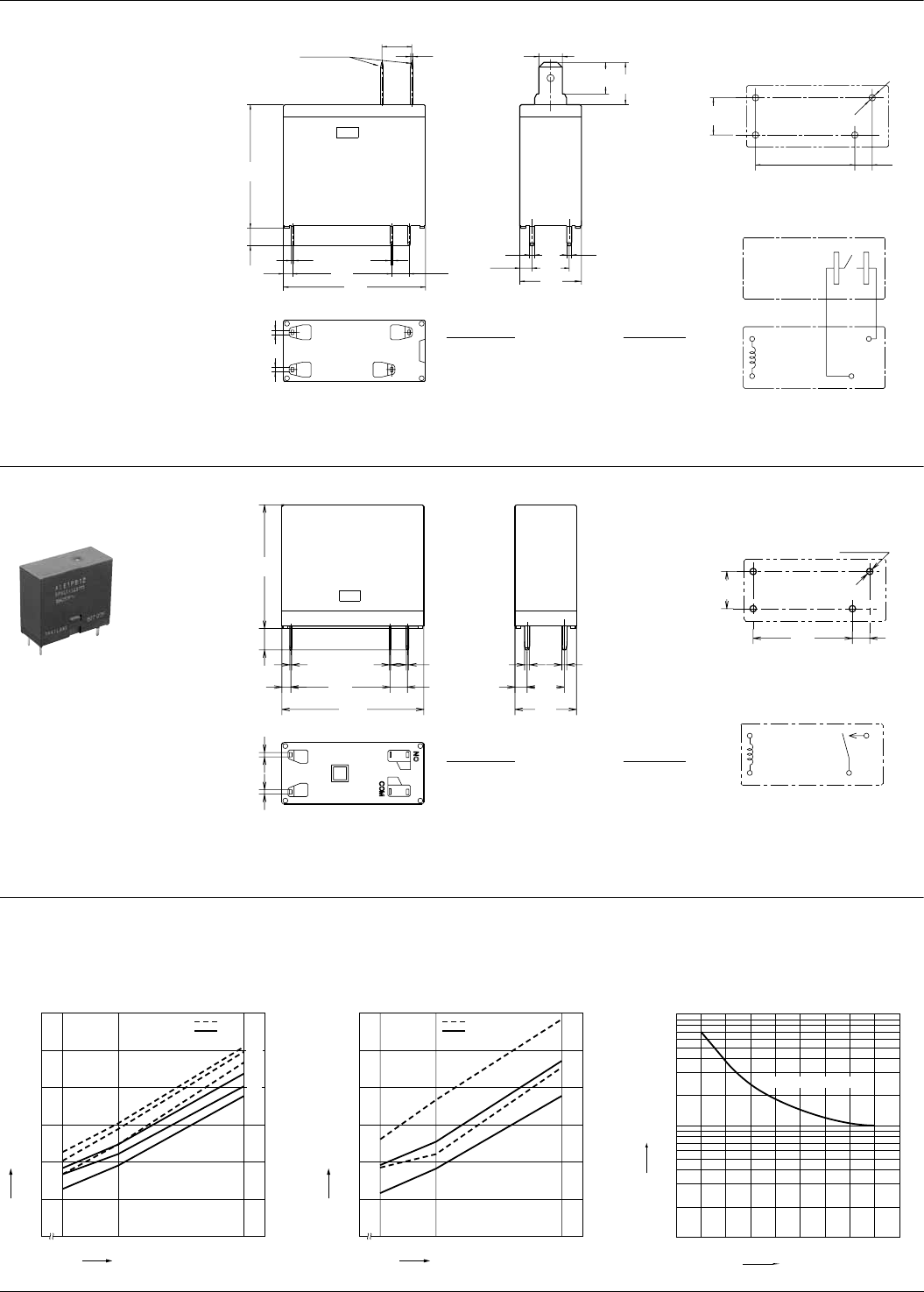
LE (ALE)
REFERENCE DATA
PCB side four terminals
mm inch
6.0
0.5
4.75
2.45
1.0 1.0
1.8
3.5
0.50.4
24.9
28.6
20.0
3.5
6.35
8.5
7.5
12.4
#187 terminal
0.8
0.8
Dimension:
Max. 1mm
1 to 3mm
Min. 3mm .118 inch
Tolerance
±0.1
±0.2
±0.3
±.004
±.008
±.012
.039 inch
.039 to .118 inch:
:
:
.236
.020
.187
.096
.039 .039
.071
.138
.020.016
.980
1.126
.787
.138
.250
.335
.295
.488
.031
.031
Com
No
Coil
Schematic (Bottom view)
20.0 3.5
4-1.3 dia.
7.5
PC board pattern (Bottom view)
Tolerance : ±0.1
.787 .138
.051 dia.
.295
±.004
2. PCB type
(No tab terminals)
0.5 1.0
2.45
1.0
3.5
0.3
0.4
1.8
4.3
24.9
0.8
0.8
20.0
28.6
7.5
12.4
.020 .039
.096
.039
.138
.012
.016
.071
.169
.980
.031
.031
.787
1.126
.295
.488
Dimension:
Max. 1mm
1 to 3mm
Min. 3mm .118 inch
Tolerance
±0.1
±0.2
±0.3
±.004
±.008
±.012
.039 inch
.039 to .118 inch:
:
:
PC board pattern (Bottom view)
Tolerance: ±0.1 ±.004
Schematic (Bottom view)
3.5
4-1.3 dia.
20.0
7.5
.138
4-.051 dia.
.787
.295
Coil
No
Com
1-1. Coil temperature rise (400mW type)
Sample: ALE14B12, 6 pcs.
Point measured: coil inside
Ambient temperature: 25°C 77°F, 85°C 185°F
1-2. Coil temperature rise (200mW type)
Sample: ALE74B12, 6 pcs.
Point measured: coil inside
Ambient temperature: 23.7°C 74.66°F, 85°C 185°F
2. Life curve
800
0
10
20
30
40
Temperature rise, °C
Coil applied voltage, %V
50
60
100 145
12A
12A
16A
0A
16A
0A
85°C
25°C
800
0
5
10
15
20
Temperature rise, °C
Coil applied voltage, %V
25
30
100 145
16A
0A
16A
0A
85°C
23.7°C
100
10
1
20 4681012 14 16
250V AC resistive load
Contact current, A
Life, ×10
4
All Rights Reserved © COPYRIGHT Matsushita Electric Works, Ltd.


