- 4 -
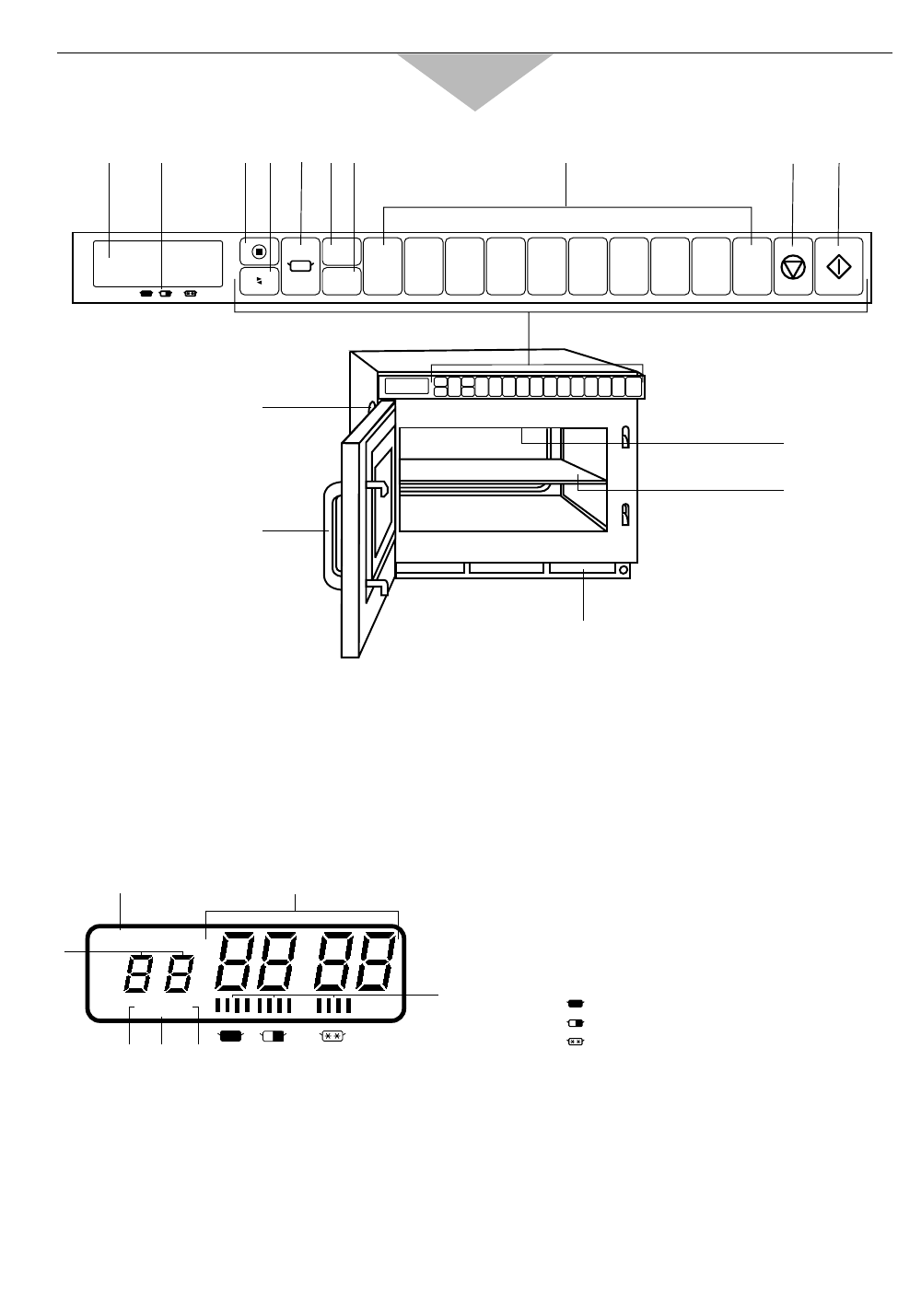
Outline Diagram of NE-2156-2/NE-1656
(1) Digital Display Window (see below)
(2) Power Level Indicator Display
(3) Program pad
(4) Shift (A/B) pad
(5) Power Level Selector pad
(6) Double Quantity pad
(7) Treble Quantity pad
(8) Number/Memory pads
(9) Stop/Reset pad
(10) Start pad
(11) Oven Lamp Cover
(12) Door Handle
(13) Air Filter
(14) Splatter Shield (top of inner cavity)
(15) Middle Shelf (NE-2156-2 only)
A –– Program Display
B –– Heating Time Display (min. sec.)
C –– Memory Pad Number Display
D –– 1st Stage Heating Indicator
E –– 2nd Stage Heating Indicator
F –– 3rd Stage Heating Indicator
G –– Power Level Indicator
:
HIGH
: MEDIUM
: DEFROST
A
1234567890
B
(13)
(11)
(12)
(14)
(15)
(8)
(1) (2)
(3)(4) (5) (6)(7)
(9)
(10)
x 2
x 3
PROG
231
AB
C
DE F
G
This oven is preset at the factory for the following:
◆ Manual operation
◆ Number/Memory pads preset HIGH power at the indicated heating times for single stage heating
1 = 10 sec. 2 = 20 sec. 3 = 30 sec. 4 = 40 sec. 5 = 50 sec.
6 = 1 min. 7 = 1 min. 15 sec.8 = 1 min. 30 sec.9 = 1 min. 45 sec.0 = 2 min.
(There are two sides, A and B. Only A-side is preset.)
◆ Program Unlock
◆ Cycle Counter set to “0” on all pads
If you wish to change these times, please consult the operating instructions to find how to program them.


