


10.6. Confirm after repair
1. After repair or replacement of parts, make sure that the
screws of the oven, etc. are neither loose nor missing.
CAUTION
Servicemen should remove their watches whenever working close to or
replacing the magnetron.
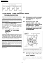
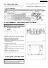
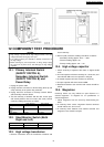
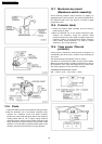
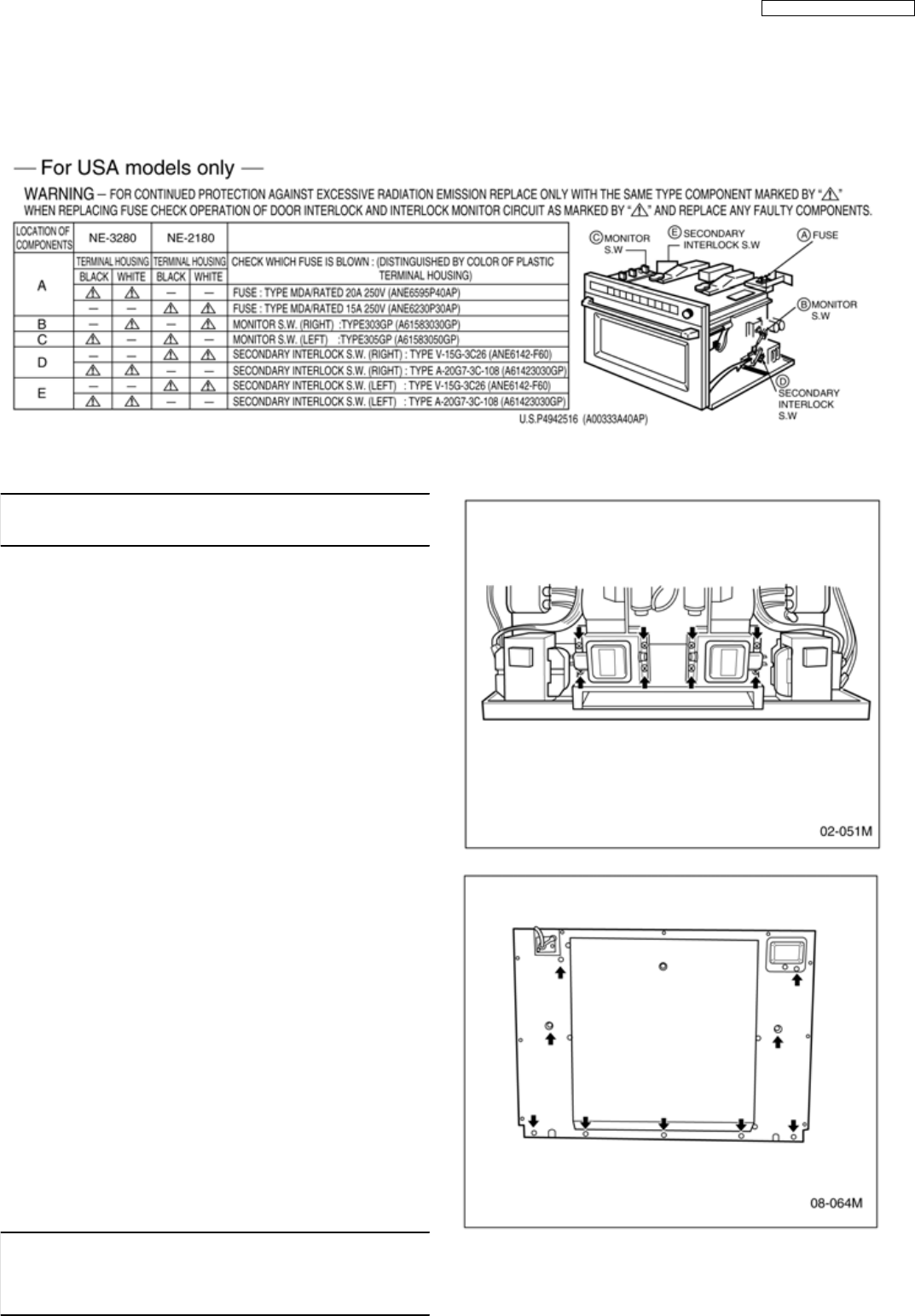
11.1. Magnetrons (Upper and
Lower)
Upper magnetrons (Right and Left)
1. Discharge electric charge remaining on the high voltage
capacitors.
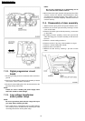
2. Remove the entire rear panel by removing screws as shown
in figure.
3. Disconnect all lead wires from magnetron and thermal
cutout.
4. Remove the 4 screws holding magnetron.
5. Remove 2 screws holding thermal cutout.
6. Remove the mounting bracket from magnetron and install it
on the new magnetron.
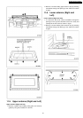
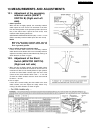
Lower magnetrons (Right and Left)
1. Discharge electric charge remaining on the high voltage
capacitors.
2. Remove the entire rear panel by removing screws as shown
in figure.
3. Disconnect all lead wires from magnetron and thermal
cutout.
4. Remove the 4 screws holding magnetron.
5. Remove 2 screws holding thermal cutout.
6. Remove the air guide from magnetron and install it on the
new magnetron.
NOTE:
To prevent microwave leakage, tighten mounting
screws properly making sure there is no gap between
the waveguide and the magnetron.
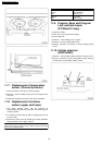
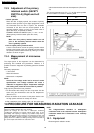
CAUTION
When connecting 2 filament lead wires to the magnetron terminals, be
sure to connect the lead wires in the correct position. The lead wire
with blue connector should be connected to “FA terminal” and white
one should be connected to “F terminal”. (See Figure)
2. Make sure that all electrical connections are tight before
inserting the plug into the wall outlet.
3. Check for microwave energy leakage. (Refer to procedure
for measuring microwave energy leakage.)
11 DISASSEMBLY AND PARTS REPLACEMENT
17
NE-3280 / NE-2180 / NE-2180C