


15 TROUBLESHOOTING GUIDE
CAUTION
1. Check grounding before checking for trouble.
2. Be careful of the high voltage circuit.
3. Discharge high voltage capacitor.
4. When checking the continuity of the switches or the high voltage transformer, disconnect one lead wire from these parts and then check
continuity with the AC plug removed. To do otherwise may result in a false reading or damage to your meter.
When disconnecting a plastic connector from a terminal, you must hold the plastic connector instead of the lead wire and then disconnect it,
otherwise lead wire may be open or the connector cannot be removed.
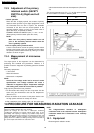
5. Be sure to ground any static electric charge built up in your body, before handling the D.P.C.
6. A 208-230V AC is present at the shaded area ( ) of the power supply circuit board (Terminals of power relays and primary circuit of low voltage
transformer). When troubleshooting, be cautious of possible electrical shock hazard.
First of all operate the microwave oven following the correct operating procedures described on pages 4 of this service manual in
order to find the exact cause of any trouble.
NOTE:
If the unit shows faulty symptom as shown below, check the parts listed in possible cause column depending on
failure indication e.g. F81, F82 in the display.
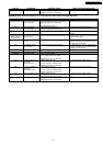
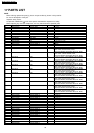
[TROUBLE] Oven does not operate at all or oven does not start cooking. NE-3280
DISPLAY CONDITIONS POSSIBLE CAUSE TIMING OF FAILURE INDICATION
F33 Open temperature
sensor (exhaust)
1. Temperature sensor failure
2. Digital programmer circuit failure
3. Loose connector CN5
It is appeared when failure occured.
F34 Short temperature
sensor (exhaust)
1. Temperature sensor failure
2. Digital programmer circuit failure
It is appeared when failure occured.
F44 1. Shorted membrane switch It is appeared 2 minutes after failure
occured.
F01
(With continuous
beep sounds)
Exhaust temperature
exceeds 120°C
1. Burning food in the oven due to over cook It is appeared when exhaust temperature
exceeds above 120°C.
F03 Input voltage exceed
+ 12.5%
1. Increase in power source voltage It is appeared when the unit is plugged in.
Note that it returns normal operation mode
by tapping the STOP pad.
F04 Input voltage is less
than — 12.5%
1. Decrease in power source voltage It is appeared when the unit is plugged in.
Note that it returns normal operation mode
by tapping the STOP pad.
F05 Memory failure 1. Digital programmer circuit failure
No display 1.25A fuse blown 1. Low-Voltage transformer failure
No display 1.25A fuse is OK 1. Thermal cutout failure
2. Low voltage transformer failure
3. Digital programmer circuit failure
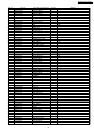
F81 No voltage supply to
high voltage trans.
(lower/left)
1. Relay failure RY-3 (A)
2. Loose connector CN256, CN257
3. Digital programmer circuit failure
It is appeared when failure occured.
F82 No voltage supply to
high voltage trans.
(lower/right)
1. Relay failure RY-5 (B)
2. Loose connector CN258, CN259
3. Digital programmer circuit failure
It is appeared when failure occured.
F83 No voltage supply to
high voltage trans.
(upper/left)
1. Relay failure RY-7 (C)
Loose connector CN260, CN261
2. Digital programmer circuit failure
It is appeared when failure occured.
F84 No voltage supply to
high voltage trans.
(upper/right)
1. Relay failure RY-9 (C)
Loose connector CN262, CN263
2. Digital programmer circuit failure
It is appeared when failure occured.
F86 Shorted contacts of RY-
3
1. Relay failure RY-3 (A)
2. Digital programmer circuit failure
It is appeared when failure occured.
F87 Shorted contacts of RY-
5
1. Relay failure RY-5 (B)
2. Digital programmer circuit failure
It is appeared when failure occured.
F88 Shorted contacts of RY-
7
1. Relay failure RY-7 (C)
2. Digital programmer circuit failure
It is appeared when failure occured.
26
NE-3280 / NE-2180 / NE-2180C