


Form No. Z2280
3
Perlick is committed to continuous improvement. Therefore, we reserve the right to change specifications without prior notice.
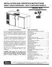
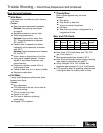
Preparing the Cabinet for Use – Direct Draw Dispensers Self-Contained
Parts List
■
Faucet Standard.
■
Faucet Head Assembly.
■
Black Connector Hose
3
⁄16” x 3’.
■
5
⁄16” Air Hose.
■
Spanner Wrench.
■
Bag of Miscellaneous Parts.
Suggested Tools Required
■
#2 Phillips Screwdriver.
■
Spanner Wrench (included).
■
#10 Crescent Wrench.
■
9
/16” Allen Wrench.
■
5
/16” &
3
/8” Nut driver.
■
Power driver.
Uncrating and Inspection
Remove all crating material before operating.
Carefully inspect cabinet for hidden damage. If
damage is discovered, file your claim immediately
with the transportation company. Perlick is
not responsible for damage in transit.
Placing the Cabinet
Push the cabinet into place using rollers when
necessary. Important: Proper air flow around the
condensing unit is necessary for efficient operation.
Never obstruct the air flow in and out of the
condensing unit.
Leveling the Cabinet
When the cabinet is in place, check installation with
a carpenter’s level. A slight pitch to the drain side is
desired. Water may accumulate if the cabinet is
pitched to the opposite side.
Installing Casters or Legs (Optional)
Attach casters to the cabinet bottom in the holes
provided. Use supplied
1
/4”- 20 x
3
/4” hex head
self-tapping machine screws. Use power driver if
available.
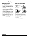
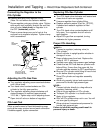
Installing the Faucet and
Dispensing Head
Before you begin: Wash tapping devices and
faucet. Flush beer, tapping device and faucet lines
with fresh water.
■
Apply RTV around the base of the dispensing
head to seal it to the top. Align the dispensing
head over the holes on the cabinet top and use
screws provided to secure standard to cabinet
top. Wipe off excess RTV to complete the seal.
■
Attach faucet to standard using spanner
wrench to tighten coupling. Attach faucet
handle to faucet.
■
Insert flexible plastic air hose six to seven
inches into bottom of faucet standard.
Secure hose with tie wrap (supplied).
Plumbing
The floor drain in the right rear corner is equipped
with a
3
/4” female pipe thread connection with side or
bottom access for beer drainer waste.
■
Remove either side or bottom drain plug with an
allen wrench and attach a
3
/4” male pipe (provided
by plumber) to an external drain connection.
Evaporator condensate has been plumbed to a
condensate pan located in the compressor housing.
CAUTION: Do not overtighten drain fitting
as it may damage the threads.
NOTE: The end of the CO
2 line extends through a
sleeve on the side of the cabinet in the
machinery compartment. Connect this
line to the pressure supply with a hose
and fitting.
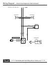
Electrical
The cabinet must be connected to a separately
fused power source (see electrical specification
plate) and grounded in accordance with National
and Local Electrical Codes. Caution: Do not
attempt to operate the equipment on any other
power source than that listed on the Electrical
Specification plate.
WARNING!
To avoid compressor damage,after returning
cabinet to an upright position, let unit stand for
24 hours before plugging it in and running the unit.