


Preparing the Cabinet – Beer Dispensers
Uncrating and Inspection
Remove all crating material before operating.
Carefully inspect cabinet for hidden damage.
If damage is discovered, file your claim immediately
with the transport company. Perlick is not
responsible for damage in transit.
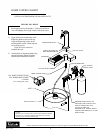
Plumbing
No plumbing connections are required. Condensate
from the cooling coil is automatically evaporated
through a condensate pan located in the
condensing unit section.
Electrical
The cabinet must be connected to a separately
fused power source (see Electrical Specification
Plate) and grounded in accordance with National
and Local Electrical Codes.
CAUTION: Do not attempt to operate the equipment
on any other power source than that listed on the
Electrical Specification Plate.
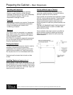
Placing the Cabinet
To assure maximum performance, fresh air must be
allowed to circulate through the machinery
compartment. Do not place anything in front of the
cabinet that would obstruct air flow at these grilles.
Do not place the unit in an unventilated small room.
Cabinet should be leveled front to back and side
to side.
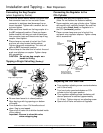
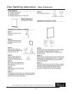
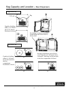
Installing Casters or Legs (optional)
Attach casters or legs to the mounting bracket with
the lockwashers and 1/4-20 hex head nuts provided.
Attach bracket and leg/caster assembly to the side of
the cabinet base using the 1/4-20 hex head self-
tapping machine screws provided.
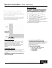
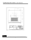
Anti-tip (without Legs or Casters)
To prevent the cabinet from tipping forward and
to provide a stable installation, the cabinet must be
secured in place with an anti-tip device.
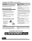
A set of metal anti-tip brackets and installation screws
(#10-3/4" wood screw) are supplied. These brackets
should be attached to the floor, at the back of the
cabinet; each bracket located to catch each rear
leveling leg when the cabinet is pushed backward into
position.
THE ANTI-TIP BRACKETS MUST CATCH EACH OF
THE LEVELING LEGS TO HAVE A STABLE AND
SAFE INSTALLATION.
Some installation sites might need to be modified to
provide a secure surface for attaching the bracket.
Refer to the illustration below for anti-tip mounting
bracket locations.
3
Perlick is committed to continuous improvement. Therefore, we reserve the right to change specifications without prior notice.