


Models SDB/SDP Installation & Operation Manual
Printed in USA 4 0213
InsTallaTIon
General Information
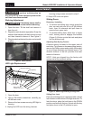
• For units equipped with a power cord, the
cord and plug may be aligned with a recess in
the back panel to allow the unit to be pushed
closer to the wall. For correct alignment, the
wall outlet must be located 4” - 10” above the
oor.
• Floor must be level in area of installation.
Preparing the Space
CAUTIO N
Make sure the oor under
the unit is level with the
surrounding nished oor. Protect a nished
oor with plywood, cardboard or some other
suitable material before moving the unit into
place. Failure to do this may result in damage
to the oor.
NOTE: If unit has been laid on its back or sides,
place unit upright and allow minimum of 24 hours
before connecting to a power source. Failure to
follow this procedure may damage the compressor
and void warranty.
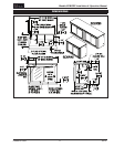
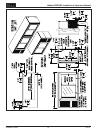
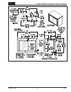
1. Make sure the space opening is correctly
sized for the unit. See Dimension drawings at
the back of this manual for correct dimensions.
NOTE: For a cabinet door to open properly, the
door must open a minimum of 90°. Use a minimum
3” ller in corner installations to assure a 90°
opening. Allow 24” clearance in front of the unit
for full door swing and shelf/drawer pull-out.
2. Check that the following are level and square:
• Front and interior opening
• Installation opening and oor surface
NOTE: The oor under the unit must be at the
same level as the surrounding nished oor.
Casters or Legs
Refer to the instructions included with the Casters
or Legs Kit.
Installing the Unit
CAUTIO N
If unit has been laid on its
back or sides, place unit
upright and allow minimum of 24 hours before
connecting power.
1. With power applied to the unit, check that
the lighting and cooling functions operate
properly, then turn off power to the wall outlet
and/or circuit breaker.
2. Position the cabinet into place using rollers
when necessary.
NOTE: Proper air ow around the condensing unit
is necessary for efcient operation. Never obstruct
the air ow in and out of the condensing unit.
3. When cabinet is in place, check installation
with carpenter’s level. When the unit is level
front-to-back and side-to-side, accumulated
water will drain out of cabinet to evaporator
drain.
4. Turn on power to the outlet and/or circuit
breaker.
Electric Condensate Evapaway
(Optional)
For installation in areas of high humidity, a 115-
volt electric condensate pan can be installed
underneath the cabinet to collect and evaporate
the condensate from the cabinet evaporator. A 6’
3-prong plug is included. A separate circuit should
be provided for the heater. The kit can be used
only on cabinets equipped with 4” minimum legs;
it cannot be used on units equipped with platform
or base plate kits. Follow instructions supplied
with the kit.
Base Plate Installation (Optional)
Once the unit is secured in place, install the base
plate brackets to the cabinet bottom in the holes
provided. Attach base plate to brackets. Refer
to the installation instructions included with the
Base Plate Kit.