


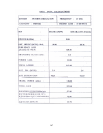
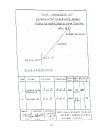
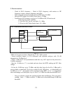
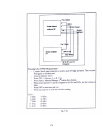
3. Test on receiver:-
- Check of RLO frequency :- Check of RLO frequency with unritsu or HP
frequency counter, measure frequency and offset
- Write assigned measured and deviation in PPM limit ±20 PPM
- Measure RLO output level at RLO mon limit ≥-12 dBm
- Feed Receive RF frequency at a level of -30 dBm at RX, RF and record
- 1.RF frequency limit ±250Khz
2. If level at AGC out (IF out) limit -5 ±1 dBm
3. IF level at AGC Mon Socket limit -10 ±1dBm
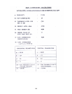
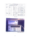
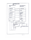
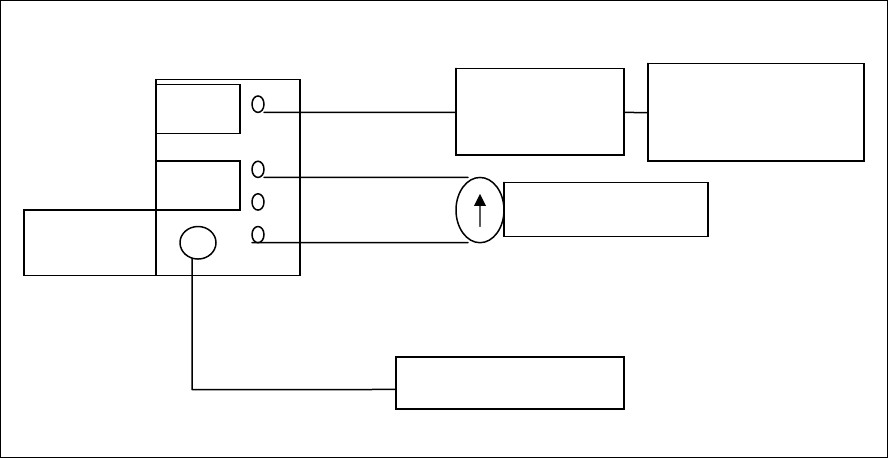
AGC calibration at Rx Rec I/P level
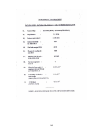
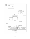
Fig. 7-7
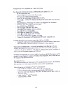
-Make test set up as per above diagram no 7-7 for 7 GHz system.
- Sweep oscillator output is to be calibrated with spectrum analyzer with -20 dB
attenuator for -20 dBm level.
- Adjust -3 dBm by IF level potentiometer and then vary AGC input level by microwave
Variable attenuator.
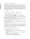
- Start by -20 dBm as -17 is overload and note down the BITE reading and DC Mon
voltage.
- Go low by 10 dB step up to -70 dBm and after that lower the level by 1 dBm until a
receive alarm is monitored. The level at which Rx fail LED glows , is a threshold level
for BER of 1x 10
-3
and squelch will be monitored when BER 1x 10
-5
i.e. degradation
starts and change over takes place, say at a level 2 to 3 dBm less than the threshold level.
- Now go to back to restore the squelch and note down difference. This is hysterics
reading.- Limit . -17 dBm overload, -75 dBm receive threshold Range 50 dB from
threshold.
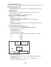
SW Generator
20 dB
RF in
Attenuator
AGC
Multimeter
IF out
MSA Receiver
175