7-2.4 HOP A/T OF 11 GHz 140 Mbps or STM-1
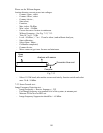
1] Receive level: - Note down Surveyed level, Nominal level and measure Rx RF level
at Rx IN by power meter with suitable sensor and pad by removing the W/G from RF IN.
m - The same Rx RF level can be easured with calibrated spectrum analyzer and by
ed
een surveyed and nominal level should be within ±3 dBm.
f provided) which should
2] ea and at Mon skt Limit -10 dBm.
Me r this is for
refe n
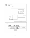
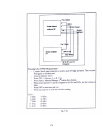
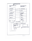
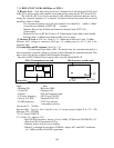
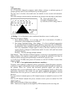
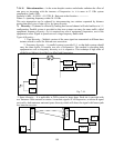
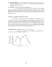
3] Group delay and IF response:- See Fig. 7-15
tim
ngular frequency.
l station MOD off.
r at other end
tuning the required frequency of a channel, deviation between measured and survey
should be within ±1 dBm.
- The deviation betw
As per the test schedule of DOT ML section..
ain and Protection channel with ATPC ON , - Measure Rx level on all M
(If provided)
rization (i- Measure Rx level at RF Rx IN due to X- Pola
an -30 dBmo from measured RF level or better. be Better th
M sure IF level at AGC out. Limit is -5 ± 1 dBm
asu e AGC voltage at connector M-69 pin 1-8, reading may be -6.0 V,
re ce only.
It is the transit time delay effect. The transit time for a transmission path is a
or current to travel through the transmission path. This e required by a specific voltage
time is given by the rate of phase shift & a
Ta tke est in MGC (Manual Gain control) only, keep al
MLA Transmitter at one end MLA receive
Front
- Blinking O
- Counter -PLL out frequency high
- P chose frequen T Tr P
- Auto at 83.5 KHz -Threshold EXT Off
- IF (BB frequency) - EXT/Line selector
Line marker selector
Received CF – 70 MHz
Sweep width – Type A ± 10 or Type B ± 6 or ± 9.5 as per system, Adjust IF to -3 F = 200
KHz rms, BF= 250 MHz
Y1=
ent 200 KHz deviation, Sweep ±10 or ±6 MHz, 7 MHz and 250 KHz BF,-3.0
itter at IF in
conditions
Rear
N -BB select NML
- X select IF -Character ON
-P cy -CR ace CM O/
IF Amp1.87dB P-P,
Y2 = Delay 16.1 nanosec. P-P
- S 0
dBm from MLA Transm
- Distance station will receive on display.
Sweep shows 0.00MHz. Adjust AGC and MGC
for -3 dBm and then from MSA generator.
- When IF is through
193 10 90
-3
P-P
I/P
IF O/P
IF
IF IN on
Transm
Fig. 7-15
itter
183


