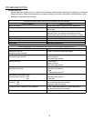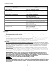
connections for integrity If the connection is good the Probe should be checked as described in the appropriate
section. If the Probe is not at fault the computer may be suspect.
{ If the display is lit but the Main Burners are still controlled by the Alternate Thermostat, check for 24 vdc at the K5
relay. This relay is the Control Transfer Relay and is energized at all times when the computer is ON. When the
computer senses an OPEN PROBE condition it will cease to energize the Control Transfer Relay and the Alternate
Thermostat will control the Heat Demand.
Digital Controls:
Check for an input voltage of 24 vac between the Red and White/Black wires at the control. When the control is
calling for a heating cycle check for a 24 vac output signal between Gray and the White/Black wires. If the control
des NOT output a signal when calling for a heat cycle it should be replaced.
Basket Lifts:
Micro Switch:
Check for continuity between all connections with the plunger in the in and out positions.
Motors: Check for the incoming voltage between the two wire leading to the motor. If voltage is present but the
motor does NOT turn the motor is defective. If the Basket Lift assembly comes UP and stops but drifts down, the
brake assembly on the motor is defective and the motor must be changed. If the Basket Lift assembly moves up
and down when operated but stops and starts at different positions check and adjust the Switch Actuation Plate
located on the output shaft of the motor.
Float Switches:
It is important to keep Float Switches clean and free from debris. The Float Ball should only be installed with the
writing in the UP position. To check the switch, electrically isolate the wiring and check for continuity.
Interlock Switchs:
These switches are mounted on the Drain Valve body and handle. When the handle is moved the Actuator
(magnet) on moves away from the switch and causes it to OPEN, this can be verified by checking for continuity
between the two wires that lead to the switch. The nominal gap between the Actuator and Switch should be
between 3 - 6 mm.
Relays:
When the correct voltage is supplied to the coil the switch section of the relay will close. Relays may be checked
by checking continuity between Switch terminals when the Relay IS and IS NOT energized.
Hot Surface Ignitors (Also known as HSI - RPB14 Only):
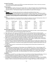
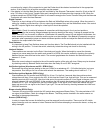
Disconnect the wiring harness leading to the part. Check for a resistance of 3 - 5 W while the Ignitor is at room
temperature. Run the fryer for five minutes and recheck the resistance. The reading should now be 5 - 7 W.
Hot Surface Ignition Modules (RPB14 Only):
Check between the TH terminal and GROUND for 24 vac. For the first 4 seconds after the module receives
voltage there will be a 24 vac output to the HSI. At this time the Check Fryer Light will light. This can be measured
between terminals HSI1 and HSI2. After this initial period, the module outputs a 24 vac signal to the gas valve
solenoid between VAL and GROUND. At the same time the HSI module sends a signal to the gas valve it begins
to sense a 0.15 - 0.35 ma signal from the Hot surface Ignitor. If this signal is NOT found the module will shut
down and send a 24 vac signal to the Check Fryer Light. This can be found by checking between the LAMP and
GROUND terminals.
Blower circuits (RPB14 Only):
The same 24 vac signal that controls the HSI module also energizes a Blower Relay. This relay switches a 240
vac signal to the Blower. Check for voltage at the Blower. The Relay can be checked in the same manner as
described in the appropriate section.
Burners (RPB14 Only) :
In order to inspect the burners for defect they must be removed from the machine. There must be NO visible
signs of damage, such as creases or holes. Remove the HSI before attempting to remove the burner, as they are
easily damaged.
11


