1-13
1.5.3.1 Gas Line Requirements - A properly installed gas supply system will deliver 7.0 ±2.0"
w.c. natural gas (12.0 ±2.0" w.c. LP) to all appliances connected to the line, operating at full demand.
1.5.3.2
Burner Adjustment - The burners must be adjusted to deliver optimum flame. Adjust the
burner flame using the following procedure.
a. Ensure that the main gas valve is shut off, remove the manifold pressure tap plug and
connect an accurate pressure gauge (range of 0-16" w.c. in 0.1" increments) or
manometer.
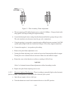
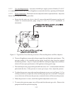
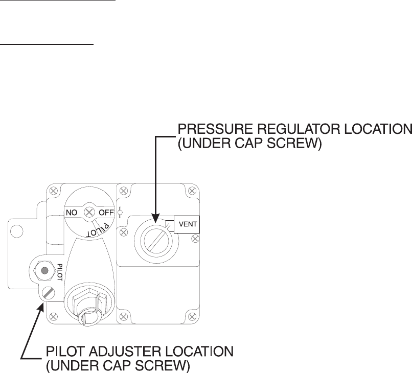
Figure 1-3 Typical Gas Valve Showing Location of Pressure Regulator and Pilot Adjusters
b. Turn on all appliances connected to the gas supply line and light their main burners. The
pressure reading of the installed pressure gauge should not drop from the required
installation pressure. Any loss of pressure indicates inadequate supply line installation
which will cause poor performance of all appliances during peak usage.
c. The installed pressure gauge reading should be the same, ±0.1", as that marked on the data
plate inside the door. If the pressure is correct go to step e, if not, adjust the pressure.
d. To adjust the pressure, remove the regulator adjustment screw cover (see Figure 1-3). Use
a flat tip screwdriver to adjust the screw until the proper pressure is reached. Turning the
screw clockwise will increase the pressure, counterclockwise will decrease the pressure.
e. When the pressure is correct, install the regulator adjustment screw cover.
f. To remove the pressure gauge, turn off fryer and shut the main gas valve. Remove the
gauge and install the pressure tap plug.
IN


