


INSTALLATION
L20-258-UK Rev.01 8/16/04 1
CHECKING YOUR NEW PITCO APPLIANCE
Your new Pitco appliance has been carefully packed into one crate. Every effort has been made to ensure that
it is delivered to you in perfect condition. As you unpack your new appliance, inspect each of the pieces for
damage. If something is damaged, DO NOT sign the bill of lading. Contact the shipper immediately; the shipper
is only responsible for 15 days after delivery. Check the packing list enclosed with your appliance to ensure that
you have received all the parts to the appliance. If you are missing any parts, contact the dealer from whom the
appliance was purchased. As you unpack the appliance and its accessories be careful to keep the weight of the
appliance evenly distributed.
Locate your Pitco model number, serial number of the appliance and the date of purchase and write them on the
cover of this manual for future reference. You will find the model number and serial number on the data plate
located inside the door.
CAUTION
To prevent equipment damage and/or personal injury, do not tilt the appliance onto any
two of its casters or legs, or pull the appliance by the splash back.
ASSEMBLY
When you receive your appliance it is completely assembled with the possible exception of the legs (or casters).
Leg/Caster Installation and Leveling
This appliance must be installed with legs or casters; it can
not be curb mounted. Curb mounting may seriously inhibit
this appliance’s ability to operate properly.
WARNING
This appliance must be installed with the legs or
casters provided by the manufacturer.
WARNING
Do not install legs or casters, or perform leveling procedure when unit is in operation or
fry tank is full. Serious injury could result.
Required tools: 7/16 “ wrench and socket and a large pair of pliers (water pump or plumber’s pliers work best).
The legs/casters must be installed before connecting the appliance to the electrical supply. The legs provide the
necessary height to meet sanitation requirements and assure adequate air supply for component cooling. Use
the following procedure.
a. Lay the appliance on its back, being careful not to damage the splashback area by pulling on it.
Protect the outside of the appliance with cardboard or a drop cloth when laying it down.
b. Attach each leg/caster with the hex head screws and nuts supplied. Each leg/caster requires
four ¼-20 x 5/8” hex head screws and nuts. Insure that all screws are tight.
c. Mount the screws from the inside of the appliance with the nut on the outside (bottom) of the
appliance. The nuts have lock washers attached to them, therefore it is not necessary to use
lock washers
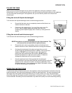
d. When all four legs/casters are securely mounted, stand the unit up, being careful not to put too
much weight on any one leg. Adjust the height and level the appliance by adjusting the leveling
devices (B) with pliers. On casters, loosen 2 screws (A) before leveling, then retighten.