


26
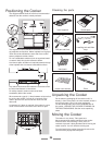
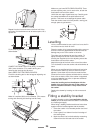
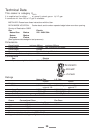
4. Lower the front roller and move the cooker forward.
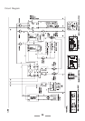
5. Measure back from the pencil line 550mm to locate
the front edge of the bracket. Fix the bracket to the
floor.
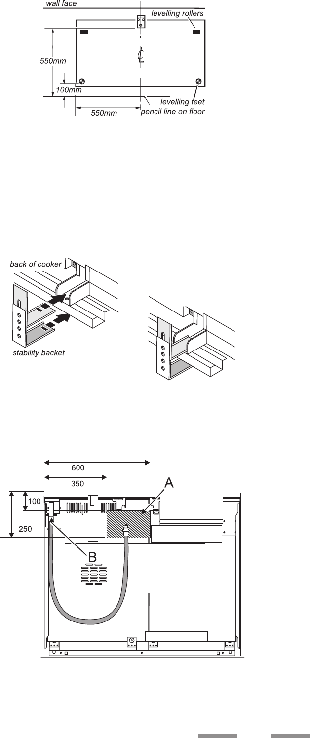
6. Measure the height from floor level to engagement
edge in back of cooker. Add 3mm to this dimension
and assemble the stability bracket to this height.
(i.e. from floor level to underside of the top
member) and ensure the bracket does not foul the
oven burner assembly.
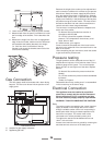
Gas Connection
The Gas supply needs to terminate with a down facing
bayonet. The rear cover boxes limit the position of the
supply point.
view from the rear
A position for gas supply connector
B appliance gas inlet
Because the height of the cooker can be adjusted and
each connection is different it is difficult to give precise
dimensions. Ideally the house supply bayonet should
be in the shaded area shown in the diagram. Although
a 900mm hose can be used, a 1250mm hose will allow
slightly more flexibility in the positioning of the bayonet
and make moving the cooker easier. The hose should
be fitted so that both inlet and outlet connections are
vertical so that the hose hangs downwards.
The connector is located just below the hotplate level
at the rear of the cooker.
For Natural Gas the flexible hose must be in
accordance with B.S.669.
For LP Gas it should be capable of 50mbar
pressure, 70 C temperature rise and carry a red
stripe, band or label.
If in doubt contact, your supplier.
Screw connect the threaded end of the hose into the
gas inlet in the underside of the connector block on the
back of the cooker.
After completing the gas connection, check the cooker
is gas sound with a pressure test.
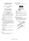
Pressure testing
The gas pressure can be measured at one of the LH
hotplate burner injectors. Lift off a burner head. Fit the
pressure gauge to the injector. Turn on the hotplate
burner and turn on and light one of the other hotplate
burners.
For Natural Gas cookers the pressure should be
20mbar.
For LP Gas cookers the pressure should be 29mbar
for Butane
37mbar for Propane.
Reassemble burner top, making sure it is reassembled
in the correct way on the burner body.
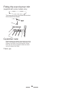
Electrical Connection
This appliance must be installed by a qualified
electrician to comply with the relevant Institute of
Electrical Engineers (I.E.E.) regulations and also
the local electricity supply company requirements.
WARNING: THIS APPLIANCE MUST BE EARTHED
Note
The cooker must be connected to the correct electrical
supply as stated on the voltage label on the cooker,
through a suitable cooker control unit incorporating a
double pole switch having a contact separation of at
least 3mm in all poles. This cooker must not be
connected to an ordinary domestic power point.
The cable size used should be between 6mm
2
and
10mm
2
, twin and earth.
Access to the mains terminal is gained by removing the
electrical terminal cover box on the back panel.