6
ISTALLATION
INSTALLATION
3) Electrical Connection
This appliance must be installed by a qualified
electrician to comply with the relevant Institute
of Electrical Engineers (I.E.E.) regulations and
also the local electricity supply company
requirements.
WARNING: THIS APPLIANCE MUST BE
EARTHED
Make sure that the mains characteristics (voltage,
nominal, power, etc.) match the ratings indicated on
the data plate on the hob base.
The appliance must be connected to an efficient
earthing circuit. If the electricity network is not
equipped with an earth connection, then it must be
installed separately in compliance with local
regulations. Earthing is a safety measure required
by law, and must be performed with particular care
by a qualified technician, who must also check that
the electricity supply characteristics are correct.
We disclaim all responsibilities for not observing
these points.
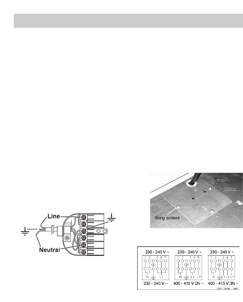
- If the appliance is not equipped with an input
cable, connect to the terminal block with an
adequate section cable keeping the “earth”
conductor longer than “live” ones, see fig. 10.
The appliance must be connected to the correct
electrical supply as stated on the voltage label on
the cooker, through a suitable cooker control unit
incorporating a double pole switch having a contact
separation of at least 3mm in all poles. It must not
be connected to an ordinary power socket.
The “earth“ cable does not have to be interrupted by
the switch.
Recommended cable type:
Rubber H05 RR_F of minimum 2.5 mm
2
conductor
size for single phase.
The unit must be protected by a suitable fuse or
circuit breaker.
Important:
These products are designed and built according to
the European standards EN 60 335-1 and
EN 60 335-2-6 and relevant amendments.
The appliance has been produced to the European
Directives:
- CEE 89/336 + 92/31 + 93/68 concerning EMC.
- CEE 73/23 + 93/68 concerning the electrical
safety.
4) Multiphase connection
Before beginning any servicing always disconnect
the electricity supply.
The appliance is supplied for single phase electrical
supply. It can be converted for use on a 3 phase
supply by changing the connection jumpers.
a)Take off the connection panel by removing the
fixing screws by screws (see fig. 11).
b) Reposition the connection jumpers as shown in
fig. 12.
c) Connect the input cable and hold in place with
the cable clamp.
d) Replace the cover panel using the fixing screws
(see fig. 11).
Fig. 10
Fig. 11
Fig. 12


