


9
INSTALLATION
Check the appliance is electrically safe and gas sound when you have finished.
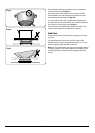
Pressure Testing
The gas pressure can be measured at one of the hotplate
burner injectors. Lift off a burner head. Fit the pressure gauge
to the injector. Turn on and light one of the other hotplate
burners. Turn on and push in the control knob for the burner
with the pressure gauge fitted to let gas through.
Turn off the burners. Reassemble burner top, making sure it is
reassembled in the correct way on the burner body.
Fixing the Hob
The hob must be sealed to the work surface to prevent liquid
from entering into the cabinet. A tape seal is supplied with
the hob.
Carefully follow these instructions to correctly apply the
seal: Turn the hob over and place in on a secure, level
surface. Detach the seal from the backing, checking that the
transparent protection still adheres to the seal itself. Carefully
position the seal along the edge of the hob. Take special care
in the corners making sure there are no gaps. The ends of the
strips must fit together without overlapping.
If the surface that the hob is to be fitted to is tiled or is not
reasonably smooth, additional sealing with a waterproof
silicone sealant may be required.
Turn the hob back the right way up and position it in the
worktop cut-out.
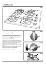
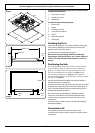
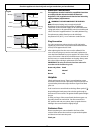
Secure the hob to the worktop using the brackets supplied.
The positioning of the bracket is dependent on the thickness
of the worktop as shown in (Fig.5-4).
Note: Slide the optional sleeve onto the bracket if fitting to
thin work surfaces.
Locate the bracket to the slot on the hob base and then
tighten the retaining screw until it is locked to the worktop.
Gas Connection
Before connecting the appliance, check that it is suitable for
your gas and electricity supply. This information is on the data
label fixed to the underside of the hotplate. Gas connection
must comply with the relevant standards and regulations in
force.
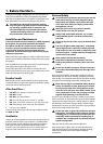
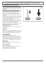
The gas connection point is located as shown in the diagram
below. The inlet union is Rp ½.
The appliance must be connected to the gas supply system
with one of the following:
A rigid steel pipe
The joints of this pipe must consist of threaded fittings
conforming to the standards. The use of seals such as hemp
with suitable cement, or Teflon tape, is permitted.
A copper pipe
The joints of this pipe must consist of unions with mechanical
seals.
A flexible hose
A hose is not supplied by with the hotplate. Hoses may be
purchased at most builders’ merchants.
The hose should be fitted so that both inlet and outlet
connections are vertical so that the hose hangs downwards.
The hose must be in accordance with the relevant standards.
In the UK these are:
For Natural Gas the flexible hose must be in accordance with
BS 669.
For LP Gas it should be capable of 50mbar pressure, 70°C
temperature rise and carry a red stripe, band or label.
Safety Information
Ensure that the gas supply pipe is never able to touch
moveable parts of the built-in cabinet (e.g. drawers). It must
not pass through compartments that could be used for
storage purposes.
When using a flexible hose, it is essential to comply with the
following instructions:
• No part of the pipe must be able to touch parts the
temperature of which exceeds 75°C
• The pipe must not be pulled or twisted, throttled or
tightly bent.
• It must not come into contact with sharp edges or
corners.
• It must be easy to inspect the entire pipe length in order
to check its state of wear.
• The pipe must be replaced within the date stamped on
the pipe itself.
If in doubt, contact your supplier.
After completing the gas connection check the hotplate is
gas sound with a pressure test.
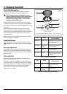
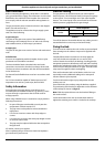
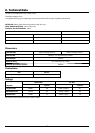
ArtNo.050-0012 Gas pressure table
Table 5-1