


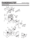
Downdraft Ventilators
Page 5
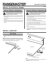
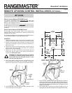
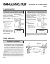
PLAN THE WIRING
Interior Blower Installation Exterior Blower Installation
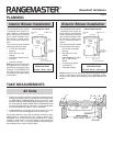
1. The Exterior Downdraft Blower system draws 6 AMPS and
requires a 120 VAC, 60 Hz circuit.
2. The unit has a 18 in. long power cord with a 3-pronged plug.
Plan to provide a grounded outlet in a location which will allow
the unit’s power cord to reach.
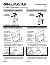
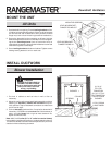
IMPORTANT - LOCATION OF ELECTRICAL OUTLET:
If Model RMDD3004EX is being installed in a 30" wide
cabinet...
or Model RMDD3604EX is being installed in a 36"
wide cabinet...
or Model RMDD4804EX is being installed in a 48"
wide cabinet...
...the outlet cannot be located on the back wall
of cabinet.
In these cases, the width of the downdraft covers nearly the
entire width of the back wall of the cabinet. So you must
either:
• mount the electrical box to a side wall or cabinet floor
- at least 12 inches from the back wall.
• mount the electrical box to a wall stud behind the
cabinet - where it will not be covered by the downdraft.
Then provide a clearance hole in the back wall of the
cabinet.
1.
The Interior Downdraft Blower system draws 4 AMPS and
requires a 120 VAC, 60 Hz circuit.
2. The unit has a 18 in. long power cord with a 3-pronged plug.
Plan to provide a grounded outlet in a location which will allow
the unit’s power cord to reach.
IMPORTANT - LOCATION OF ELECTRICAL OUTLET:
If Model RMDD3004 is being installed in a 30" wide
cabinet...
or Model RMDD3604 is being installed in a 36" wide
cabinet...
or Model RMDD4804 is being installed in a 48" wide
cabinet...
...the outlet cannot be located on the back wall
of cabinet.
In these cases, the width of the downdraft covers nearly the
entire width of the back wall of the cabinet. So you must
either:
• mount the electrical box to a side wall or cabinet floor
- at least 12 inches from the back wall.
• mount the electrical box to a wall stud behind the
cabinet - where it will not be covered by the downdraft.
Then provide a clearance hole in the back wall of the
cabinet.
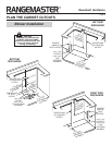
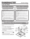
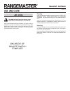
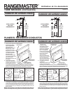
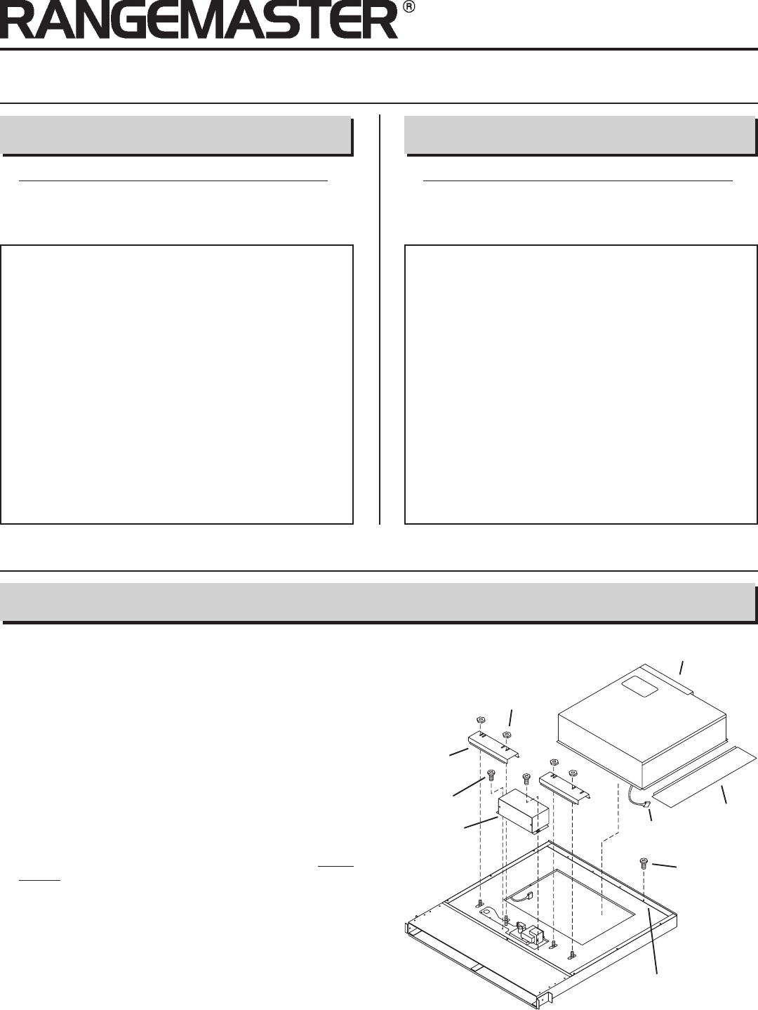
PREPARE THE DOWNDRAFT
Interior/Exterior Blower Duct Connection Installation
The downdraft is shipped with duct connector pointing toward the
bottom of the unit. If you wish to change this orientation, follow the
steps below:
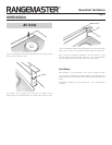
1. Place the downdraft on its back on a table of flat work surface.
2. Remove the 4 nuts and 2 clamp channels.
3. Remove 2 screws and the gear motor cover.
4. Carefully position the blower under the bottom flange of the
downdraft with the 3¼" x 10" discharge (3¼" x 14" for
exterior blower) pointed in the desired direction.
5. Connect motor plug.
6. Replace the gear motor cover and 2 sheet metal screws.
7. Replace the 2 clamp channels and start the 4 nuts,
do not
tighten.
8. Slide blower left of right to desired position. Use cover plate
(supplied) to close up any open space.
9. Tighten 4 nuts to secure top of blower. Use additional screws
(supplied) through bottom flange to secure bottom in blower.
NUTS
BLOWER
COVER
PLATE
CLAMP
CHANNELS
SCREWS
GEARMOTOR
COVER
MOTOR
PLUG
3¼" X 10" DISCHARGE
(3¼" X 14" FOR EXTERIOR BLOWER)
ADDITIONAL
SCREWS
BOTTOM
FLANGE