


LAZER BOILING WATER UNIT: FAULT FINDING GUIDE.
LAZER BOILING WATER UNIT
INSTALLATION AND OWNERS GUIDE
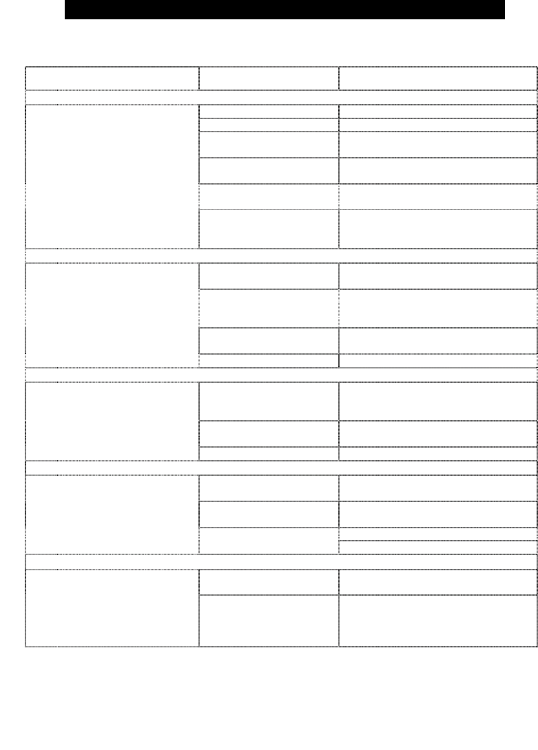
**It is strongly recommended that any REMEDY be carried out by a qualified service person**
SYMPTOMS POSSIBLE CAUSE REMEDY
Thank you for choosing our Lazer
Boiling Water Unit. Please take a few
minutes to read this booklet because it
contains important information about
the correct installation and operation of
your Lazer unit.
C. MINIMUM CLEARANCES
For ventilation reasons, all units require a
minimum clearance of 50mm on all sides.
For ease of servicing (where there is
sufficient space) we recommend 300mm
clearance from the top of all units.
For
element replacement reasons we
recommend clearance of 150mm from the
right hand side of 3 to 10 litre units and
300mm from the left hand side of the 15 to
40 litre units.
There is no power supply Check the electrical supply.
There is no water supply Check the water supply.
The inlet strainer is
blocked
Check the Inlet Strainer, clean or
replace.
Electronic Controller
failure
Test the electronic controller.
Solenoid Valve failure
Check resistance of the solenoid,
replace if broken.
1.
The unit does not fill with
water
The Filter is blocked (If
unit is supplied with an
inlet water filter)
Check the filter, replace if blocked
(see section 5E for re setting the
filter)
1. WARNING:
This Lazer unit produces boiling water
(third degree burns may occur) and care
should be taken at all times when using
it. This unit is not intended for use by
infirm persons and young children
should be supervised to ensure that
they do not play with the unit.
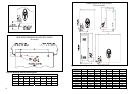
D. MOUNTING
The Lazer when installed is suspended
from mounting screws located into keyhole
slots at the back of the unit
(refer to the Mounting Dimension
Specification on page 6).
Thermal cut-out has
tripped
Reset the thermal cut-out.
Heating element failure
If the heating element is properly
wired, then check its resistance.
Replace if broken.
Electronic Controller
failure
Test the electronic controller.
2
.
The unit fills water to low
level and does not heat
Thermistor failure Replace the thermistor.
2. WATER QUALITY
Caution is suggested if the Boiling
Water Unit is to be connected to a water
supply with a high content of silica or
calcium. Water supplies of this nature
may be detrimental to the unit’s
operation and may cause the warranty
to become void. For further information
relating to the guidelines of water
quality, contact your local Rheem office
for advice.
Be sure that the mounting screws are
securely inserted into the keyhole slots.
The screws MUST be anchored in such a
way, that they will hold the weight of the
unit when filled with water, (refer to the
specification table on page 5).
Low Air Pressure
Recalibrate the unit (see section 5F
sub section v) for how to recalibrate
the unit
Electronic Controller
failure
Test the electronic controller.
3.
The unit boils
continuously
Thermistor failure Replace the thermistor.
WARNING:
Before drilling into the wall make sure that
the screw positions avoid any pipe-work or
electrical cables. Allow 4 mm clearance
between the screw head and the wall for
locating the unit.
3. INSTALLATION
Incoming water pressure
is too high
Reduce incoming water pressure.
Solenoid valve failure
Turn the unit off. If water still
overflows, replace the solenoid valve.
Clean the level probe
4.
The unit overflows
Level probe failure
Replace the level probe
This boiling water unit shall be installed
by a qualified service person. The
installation must comply with AS/NZS
3500.4 and all relevant statutory and
local body requirements of the state in
which the Boiling Water Unit is installed.
E. WATER SUPPLY CONNECTION
Cold mains pressure water (refer to
specification table on page 5 for minimum
water pressures) must be piped and
connected to the ½” BSP inlet fitting
located on the left hand side underneath
the unit. An accessible isolating valve must
be installed near the unit.
The unit did not fill with
enough water
See 1. & 2. above.
5.
There is no water from
the tap
The tap diaphragm is
disconnected from its
spindle
Drain water out of the unit
(see paragraph 6 on page 4).
When unit is empty, disassemble and
repair the tap.
A. LOCATION
This unit is designed for interior
installation only.
B. OPENING THE UNIT
This unit contains an inlet strainer on the
water inlet connection (refer to figure 1). To
ensure continuing satisfactory operation, it
is suggested that the inlet strainer be
serviced every six months by a qualified
service person. Where poor water quality is
present it is recommended to install an
additional auxiliary filter.
To remove the jacket from models 3, 5,
7.5 & 10 L remove the 4 retaining
screws at the top and bottom and pull
the jacket forward. For models 15, 25
and 40 L unscrew the lid at the top and
service plate on the left hand side.
10.
3.