


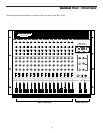
Guided Tour - Main Section
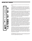
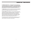
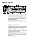
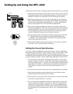
1: Meter - This seven-segment bar meter shows the continuous output level of
the Main L/R stereo output. For optimum signal-to-noise ratio, try to adjust all
levels so that program material is usually at or around 0 VU, with occasional but
not steady excursions to the red +3 or +6 segments. See the “Setting the
Correct Gain Structure” section on page 12 for more information.
2: Meter LEDs - These show the status of various conditions within the MPL
1640. The bottom left LED (labeled “PFL”) lights steadily red whenever one or
more channels is soloed. The bottom center LED (labeled “Phantom”) lights
steadily red when Phantom power is being supplied to all mic connectors (see #1
on page 8 of this manual for more information). The bottom right LED (labeled
“Power”) lights steadily red whenever the MPL 1640 is powered on.
3: Stereo Auxiliary Return Level (green) - These knobs determine the input
level of signal arriving via the MPL 1640’s three stereo Auxiliary returns. Each
return is at unity gain (no boost or attenuation) when set to the 0 position. The
input signal is boosted when the knob is turned to the right of 0 and attenuated
when turned to the left of 0. When turned fully clockwise (to the “+20” position),
the return signal is boosted by 20 dB; when turned fully counterclockwise (to the
“-∞” position), the return signal is infinitely attenuated—that is, there is no sound.
For information on how to properly set these, see the sections on pages 12 and
20 entitled “Setting the Correct Gain Structure” and “Using the Auxiliary Sends
and Returns.”
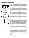
4: Stereo Auxiliary Return Balance (dark gray) - These knobs determine the
relative levels of the left and right input signals connected to the MPL 1640’s
three stereo Auxiliary returns. When the knob is placed at its center (detented)
position, both left and right input signals for that Aux return are at equal strength.
When moved left of center, the left input signal remains at the same strength but
the right input signal is attenuated; when the knob is moved right of center, the
right input signal remains at the same strength but the left input signal is attenu-
ated. When placed fully counter-clockwise, only the left input signal is heard
(panned hard left); when placed fully clockwise, only the right input signal is
heard (panned hard right). These “radical” positions are useful when you are
using a stereo Aux return as two mono returns—see the “Using the Auxiliary
Sends and Returns” section on page 20 for more information.
When only the left input of an Aux return is connected, its Balance knob func-
tions as a constant level Pan control, allowing you to continuously place the
incoming signal anywhere in the left-right stereo field.
5: 3/4 Level (green) - This knob determines the final output level of the Bus 3/4
signal. We made this knob extra big so you won’t miss it even under low-light
performance conditions. Signals from all channels that have their Bus
switch (see page 5) set to the “3/4” position are routed here prior to being sent to
the rear panel 3/4 output jacks (as described on on page 8). The center detent-
ed “0” position of the knob indicates unity gain (no level attenuation or boost).
Moving the knob counterclockwise from the “0” position (towards “-∞”) causes
the signal to be attenuated (at the fully counterclockwise position, it is attenuated
infinitely—in other words, there is no sound). Moving the knob clockwise from
the “0” position (towards “+15”) causes the signal to be boosted by as much as
15 dB. For more information, see the “Using Bus 3/4” section on page 17 of this
manual.
LR
+20
RETURN 1 LEVEL
0
−∞
+20
0
−∞
RETURN 2 LEVEL
+20
0
−∞
RETURN 3 LEVEL
R
BALANCE
L
R
BALANCE
L
R
BALANCE
L
HEADPHONES
3 - 4
LEVEL
0
10
−∞
+15
STEREO AUXILIARY RETURNS
STERE0 PFL
LEFT
RIGHT
PFL
PHANTOM
POWER
-20 -10 -6 -3
0+3+6
-20 -10 -6 -3
0+3+6
16 CHANNEL AUDIO MIXER
MPL 1640
-∞
dB
+15
0
MAIN
1
2
4
3
5
6
7
8
0
6