


61
TROUBLESHOOTING
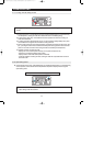
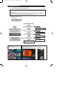
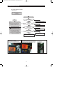
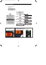
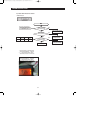
4) If Ambient Sensor has trouble
Bad contact of connector/ insert correctly
Is MAIN PCB
Connector CN31 inserted
correctly?
Is Ambient Sensor
unit normal?
Is the voltage between
MAIN PCB Connector CN31#1(Yellow) and REG1,
HEAT SINK normal?
Is the input voltage of
IC01 MICOM #72 normal?
Start
NO
YES
YES
YES
YES
Replace the temperature sensor
NO
Check the contact of PCB & Wire Terminal correctly.
NO(0.6V > Measurement < 4.6V)
Check the iced-solder, solder bridging,
disturbed solder. Replace the PCB
NO
No trouble with PCB and temperature sensor
Recheck the bad contact of the connection
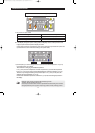
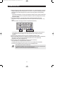
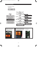
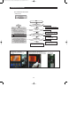
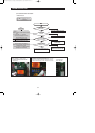
** Measuring point of resistance value according to
Sensor **
Ambient : CN31#1 #4 measuring resistance value
** Placed in the right top table of upper hinge.
** 0: Short trouble / : Open trouble
Sensor MICOM/Connector number
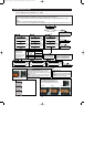
Voltage measured between 4.6V ~ 0.6V.
Measuring voltage of IC01 MICOM #72,
CN31-"1"(Yellow) and REG1, HEAT SINK from
PCB typical Ground part are similar.
Check the measure on the SENSOR MARKING
#7(R307) due to the SMD MICOM
Checking method of Ambient Sensor resistance
CN31#1(Yellow) #4(Yellow)
- Compare the temperature table after the
measure
DATA1.
Temperature table
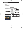
ERROR Code
Refer to circuit diagram in the manual
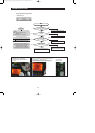
Ambient
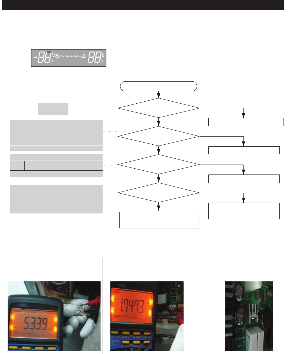
Connector Cn31#1(Yellow) to REG1
HEAT-SINK PCB common Ground
Checking method of Ambient Sensor voltage
- Measure the voltage of Sensor Check Point #7
(IC01 MICOM #72) or CN31#1(Yellow) REG1, HEAT SINK.
- Compare the temperature table after the measure. Measuring
voltage of CN31#1(Yellow) REG1, HEAT SINK are below.
typical PCB Ground
REG1 HEAT-SINK
2¢(-17¡) is recommended 38¢(3¡) is recommended
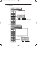
Start
YES
YES
YES