


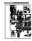

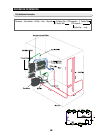

CIRCUIT DESCRIPTIONS
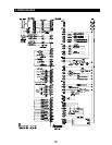
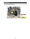
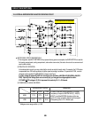
1) As shown in the Figure, C/F, C/R FAN are connected to the CN75 connector, and FAN MOTOR consists of
ND, VCC, FG.
2) If you intend to operate the C/F-FAN or C/R-FAN according to a certain condition in the MAIN PCB, which
controls the refrigerator, follow the instructions below.
3) For example, to operate C/F-FAN, a 5V voltage comes out of MICOM #6 first. Then, the 5V voltage is input to
IC75 #1 PIN, and the #18 PIN has a changed electric potential from OV to GND.
4) 12V is connected to CN76 , and input to C/F-FAN Vcc. FAN MOTOR GND is connected to IC75 #18 PIN
through CN76 .
5) Thus, with the IC75 #18 PIN changed to GND by the signal from MICOM#6 PIN, the
FAN MOTOR will be operated in the order 12V CN76 C/F-FAN Vcc C/F-FAN GND CN76
IC75 #18 PIN
GND.
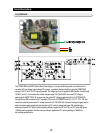
6) Here, with normal operation of the FAN MOTOR, a square wave is generated in MOTOR FG, and this wave is
input as follows, MOTOR FG CN76 R413 MICOM #8.
7) Using this FG signal, it can be determined whether the FAN MOTOR is operating normally, and in case of FG
signal errors, FAN motor errors are detected to use as refrigerator error data.
8) When the MICOM #6 signal changes to 0V again, IC75 # 1 PIN is OFF, and IC75 #18 PIN is
OFF. Thus, current cannot flow, and the FAN MOTOR will stop..
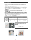
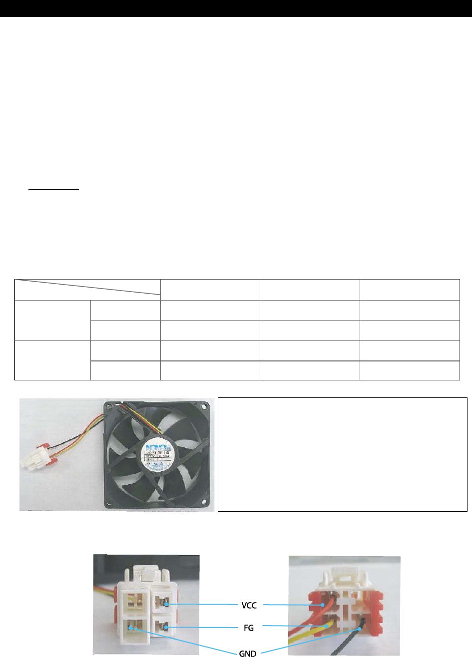
The principle of operation is equally applied to the C/F
and C/R FAN, and the BOX FAN uses the same
specification.
BOX FAN SPEC
12V / 0.2A
107
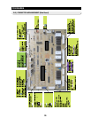
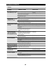
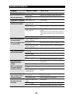
MICOM STATUS IC75 INPUT IC75 OUTPUT
C/F-FAN
C/R-FAN
ON
OFF
ON
OFF
#6 5V
#6 0V
#4 5V
#4 0V
#1 5V
#1 0V
#4 5V
#4 0V
#18 GND(0.8V)
#18 11~12V
#15 GND(0.8V)
#15 11~12V
7979