21
OPERATION PRINCIPLES BY PARTS OF CIRCUIT
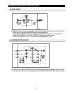
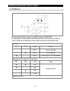
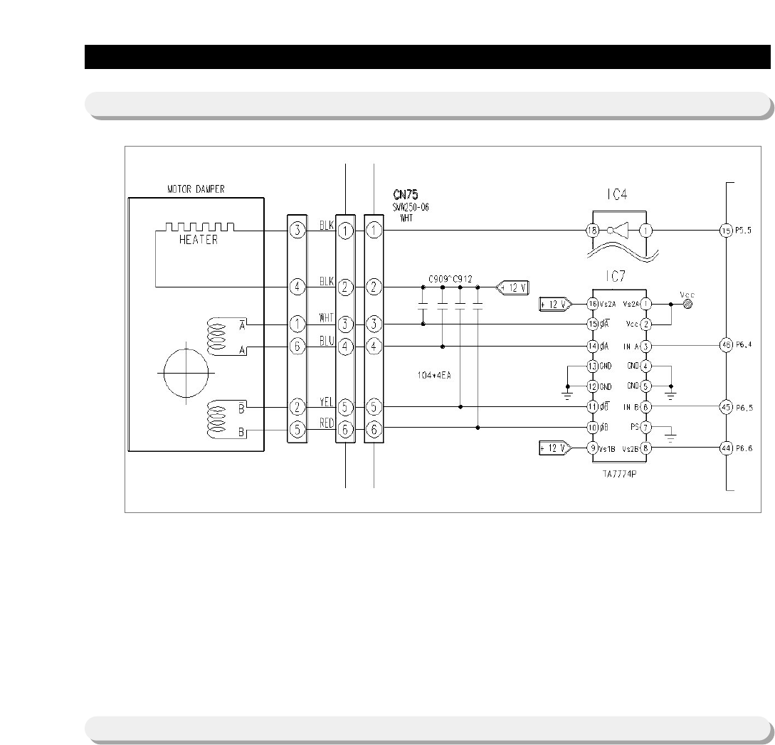
5-7) DAMPER CIRCUIT
5-8) DISPLAY Circuit
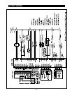
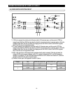
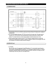
1) The temperature of R-room is controlled by opening and closing of damper with stepping motor, supplying &
blocking cold air.
2) TA7774P (IC07) operates the damper. TA7774P is the driver IC only for step motor. If the regular signal is
provided to TA7774P from Micom, send combined signal to Quad-Polar step motor to rotate on certain
direction. This makes clockwise or counter clockwise rotation to make the damper open or close.
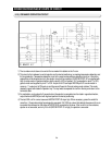
3) Since the damper always touches the cold air, DC 12V/1W heater is installed, always on to prevent the
malfunction from moisture and is controlled on conditions. (Operation conditions can be changed). Micon #15
pin connected to IC4 controls the damper heater like category 3.
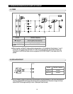
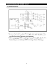
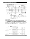
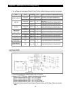
1) KEY SCAN
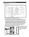
When Grid #6 is output, this signal goes through PCB resistance 10 and provided to power frequency.
When the switch is pressed, R502(6.8 ) and R501 (12 ) decrease the signal and less than 5.1V peak to
peak signal is provided to MICOM, the MICOM recognizes the grid #6 is provided, and change the function
corresponding to switch key. [Refer the circuit diagram below]


