


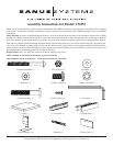
TV Attachment Hardware:
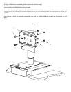
(4) M4 x 10 Bolt - p (4) M4 x 30 Bolt - q (4) M6 x 12 Bolt - r (4) M6 x 35 Bolt - s
(4) M4 Lock Washer - t (4) M6 Lock Washer - u (4) M4 Spacer - v (4) M6 Spacer - w
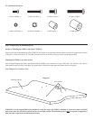
Step 1: Prepare Holes in Mounting Surface
Section A: Mounting the VMPO to the Sanus CFAR47cb
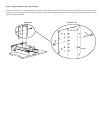
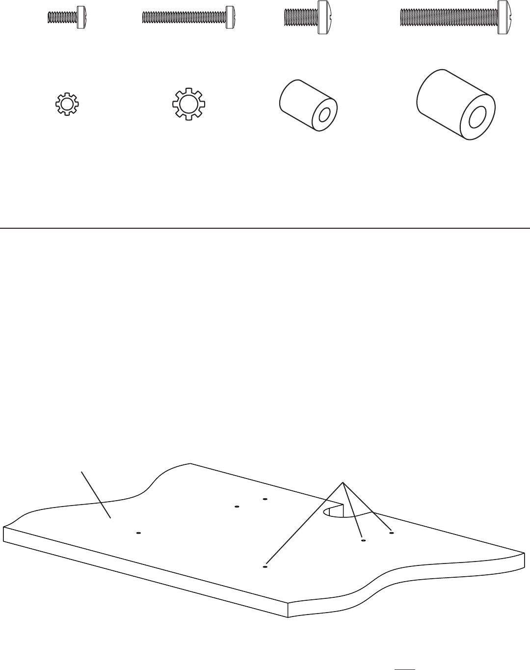
On the bottom side of the Mid Shelf on the CFAR47cb you should see 6 starter holes that have been pre-drilled in a pattern that is shown
in Diagram 1. With a Drill and a 1/4” Drill Bit, proceed to drill out all 6 holes so they go all the way through the shelf.
Mounting the VMPO to any other surface
Tape the Paper Template provided to the desired shelf the VMPO is to be mounted on. Using a Drill and a 1/4” Drill Bit, drill a hole in
each marked location (6 total) in the Shelf. You should have 6 drilled holes that match the pattern shown in Diagram 1.
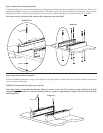
Note: Diagram 1 is a Cutaway View
Diagram 1
Mounting Surface
Hole Pattern
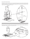
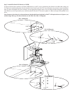
WARNING: It is the responsibility of the installer to verify the surface the VMPO is mounted to is secured so that it will NOT
tip forward when the television is pulled out into its extended position. The mounting surface must be capable of supporting 5
times the total weight of the television and the mount.