


- 1 -
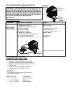
1. SPECIFICATIONS
Microwave output ................1,200W to 120W
Frequency ........................... 2,450MHz
Power supply ....................... 120V, 60Hz
Rated current ......................15 Amp.
Safety Device ......................
Thermal protector(Magnetron)
150°C(270°F) Open
(Thermostat) 80°C(144°F)Close
Thermistor (Magnetron) 200°C(360°F) Open
108°C(194°F)Close
Thermistor(Duct)................120°C(216°F) Open
Fuse (Cartridge Type) ................. 250V 10A
Micro switch, Relay
Interlock Switch
Interlock monitor Switch
Door sensing Switch and
Relay RL-3 and RL-4
Max. input time....................Electronic Digital, up to
Manual
10min./Memory 30min.
Overall Dimensions........422(W)x540(D)x335(H) mm
Oven cavity size ............330(W)x330(D)x230(H) mm
Effective Capacity of Oven Cavity.........19.1liters
Net weight ........................... 29Kg
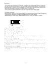
NOTE: The power output specification, 1200W on this
model is measured with IEC measurement. The power
output is measured with two(2) liters water is equiva-
lent to 1200W in measurement with IEC, when mea-
sured with the following power output.
(1)1. Fill two beakers, one liter of tap water respec-
tively
2. Use an accurate thermometer and measure each
water temperature respectively.
(2) Place beakers side by side in center of the
ceramic tray.
(3) Close the door,set the “TIME” for two minutes.
Touch the “START” key and heat the water for
exactly two minutes.
(4)Take the beakers out, immediately stir the water
and measure the water temperatures respectively.
(5) Calculate the temperatures rise of water in each
beaker. Then calculate the average value of the two
temperature rises.(Ģt)
(6) The teperature rise shall be in the following range;
Average Temp. Rise
Minimum 15.4°C
Maximum 18.8°C
Power output is affected by the line voltage under load.
(7) For correct Power output measurement, the line
voltage under load must be 120±2 Volts.
2. POWER OUTPUT MEASUREMENT
Power output Measurement ...................................... 1
Precautions and Repair Service Tips ....................... 1
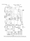
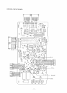
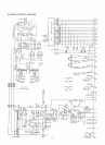
Circuit Diagram ......................................................... 2
Test Procedures ............................................3
Disassembly Instructions............................... 3 •`4
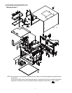
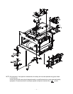
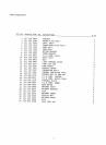
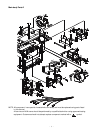
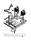
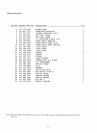
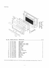
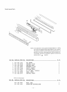
Exploded View and Parts List......................... 5 •`12
Overall Circuit Diagram.................................13 •`16