- 3 -
4. TEST PROCEDURES AND TROUBLESHOOTING
CAUTION
-DISCONNECT THE POWER SUPPLY CORD FROM THE WALL
OUTLET WHENEVER REMOVING THE CABINET FROM THE UNIT.
PROCEED WITH TESTS ONLY AFTER DISCHARGING THE HIGH
VOLTAGE CAPACITORS AND REMOVING THE LEAD WIRES ON
THE PRIMARY WINDING OF THE HIGH VOLTAGE TRANSFORM-
ERS FOR LOWER AND UPPER MAGNETRONS.
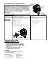
(SEE FIGURE 3)
COMPONENT
HIGH-VOLTAGE
TRANSFORMER
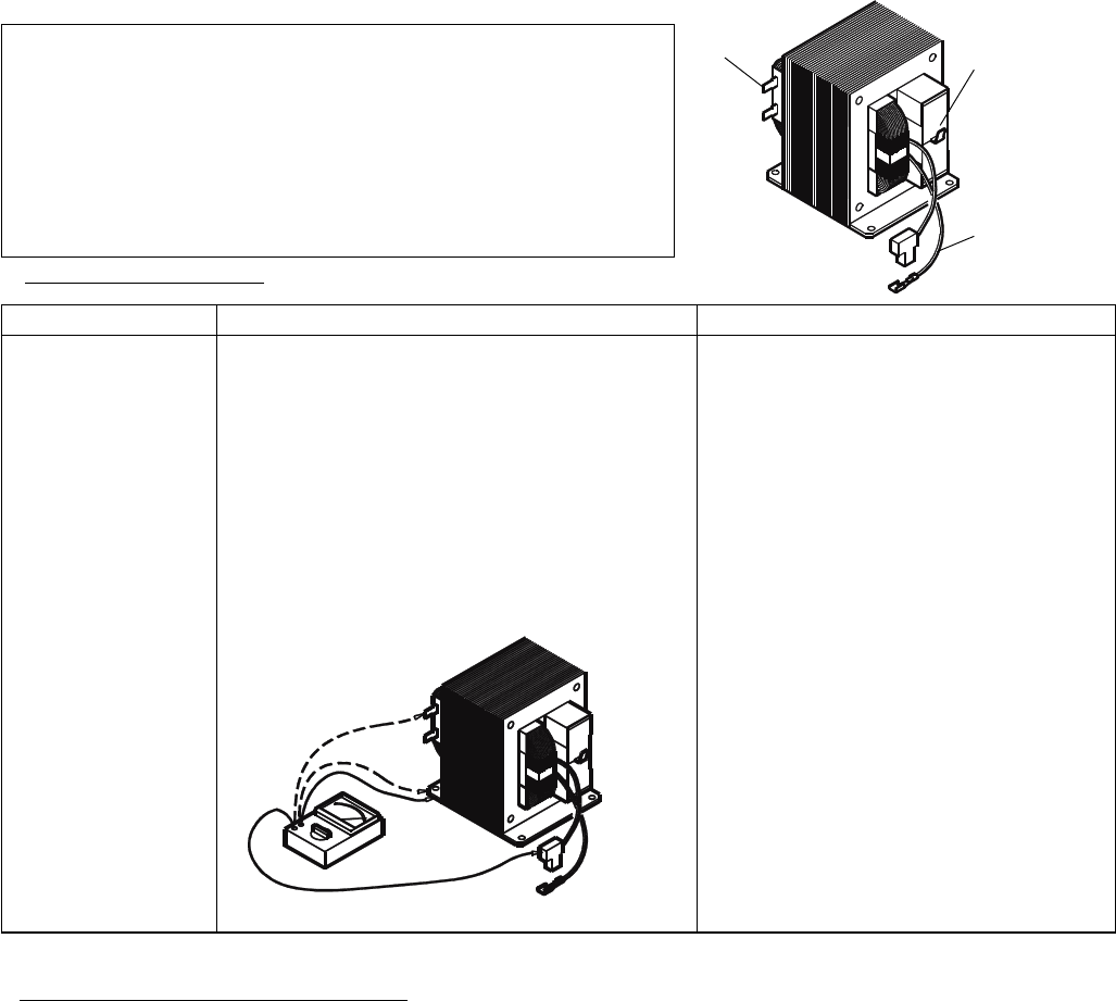
1) Measure the resistance:
With an ohm-meter on R x1 scale.
a. Primary winding;
b. Filament winding;
c. Secondary winding;
2) Measure the resistance:
with an ohm-meter on highest scale.
a. Primary winding to ground;
b. Filament winding to ground;
CHECKOUT PROCEDURE RESULT
Normal reading:
Approximately 1.0 ohms
Less than 1 ohm.
Approximately 83 ohms
Normal reading:
Infinite ohms.
Infinite ohms.
Note: Remove varnish of measured point.
PRIMARY
WINDINGS
Secondary
Windings
Filament
Windings
Figure 2
Figure 3
A. TEST PROCEDURES
F. CHANGING POWER SUPPLY CORD
(See exploded view on page 5)
(1) Unfasten 1 screw for ground and pull out the
2 wires of the power cord from the terminal plate.
(2) Remove 1 screw for the bottom bracket of the
cord bushing.
(3) Install the new power supply cord with the
reverse procedure of above (1) to (2).
WARNING:
For changing the power supply cord, never use
other than the following.
Key No. Order No. Parts Name
5 617 140 1561 Power cord Ass’y
6 617 140 1332 Cord bush
7 617 140 1349 Bottom bracket
5. DISASSEMBY INSTRUCTIONS


