


36
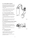
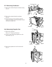
8-2. Checking Motor Capacitor
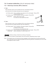
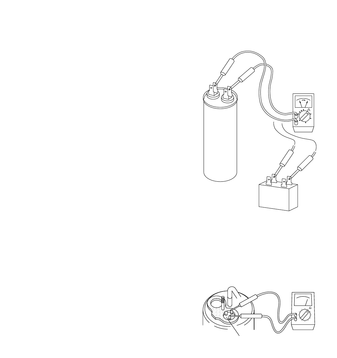
Remove the lead wires from the capacitor terminals, and
then place probes on the capacitor terminals as shown in
Fig. 4. Observe the deflection of the pointer, setting the
resistance measuring range of the multimeter to the
maximum value.
The capacitor is “good” if the pointer bounces to a great
extent and then gradually returns to its original position.
The range of deflection and deflection time differ
according to the capacity of the capacitor.
8-3. Checking Fan Motor Winding
Referring to the electrical diagram, disconnect fan motor
connectors, and measure the resistance between each
lead wire with a multimeter.
The multimeter should be set in the X1 range. If the fan
motor is hot, allow a few minutes until it gets cooled
down.
When the resistances between each lead wire are those
listed in "2-2. Major Component Specifications" the fan
motor should be normal.
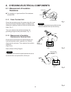
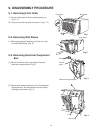
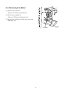
Checking compressor motor winding can be done in the
similar manner.
Remove the terminal cover of the compressor motor,
setting the resistance measuring range of the multimeter
to "X1Ω" and check the continuity between each pair out
of the 3 terminals as shown in Fig. 5.
Refer to "2-2. Major Component Specifications" for coil
resistance.
8-6. Checking Thermistor
(Only for heat pump model)
Unplug the 2P connector connected to PCB Ass´y and
measure the resistance of the thermistor with a
multimeter, which is set in the X1 kΩ range.
If the thermistor is normal, the multimeter should read
approximately 15kΩ at 32˚F.
Compressor motor
capacitor
Fan motor
capacitor
Multimeter
Fig. 4
Compressor motor
coil terminal
Multimeter
Fig. 5
8-4. Checking Compressor Motor Winding