7InRow RC Operation and Maintenance Manual
User interface inspection checklist
The user interface inspection verifies that the sensors and internal communication links are installed properly.
Check that the outdoor heat exchanger is connected to the cooling unit and to the other cooling units in the
room if you are using cooling group controls.
Start-up inspection checklist
The start-up inspection ensures that the equipment is operating properly after the initial start-up. This inspection
verifies that all modes of operation are working correctly and that the cooling unit is ready for normal operation.
Final inspection checklist
The final inspection verifies that the system is clean, and the start-up form has been sent to Schneider Electric.
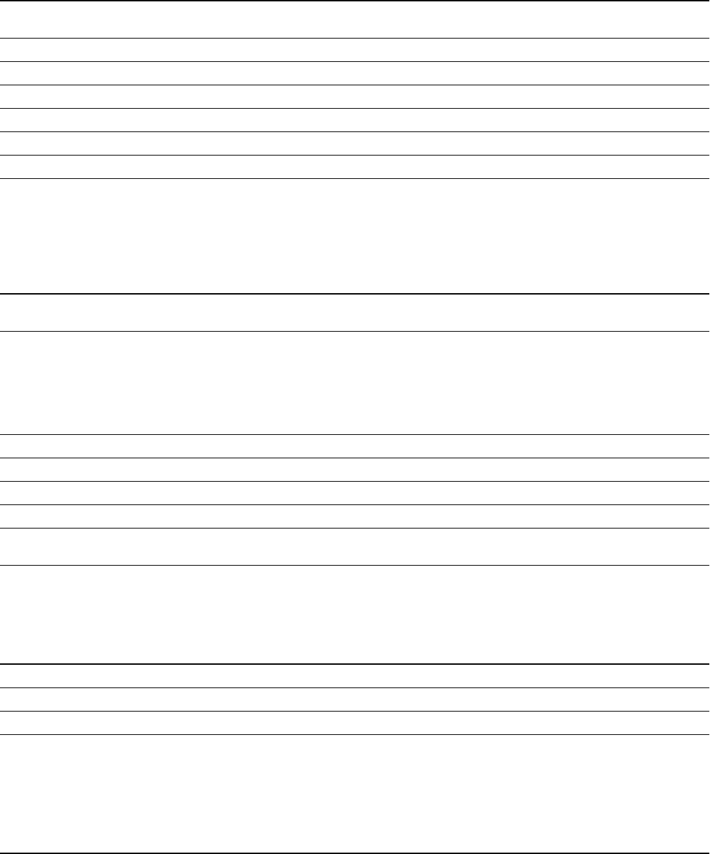
Ensure that:
An A-Link bus is connected to each cooling unit and a terminator is plugged into all unused A-Link
connectors.
The input contacts and output relays are connected correctly.
The building management system is connected correctly and a terminator is wired into the final cooling unit.
The temperature sensors located on the front of the equipment are connected correctly.
The rack temperature sensors are installed correctly.
The network port is connected correctly and an IP address has been assigned to the cooling unit.
The optional rope water detection device is installed properly.
While the equipment is operating, ensure that:
The cooling unit is free from malfunctions, including chilled water leaks, unusual vibrations, or other
irregularities, in each mode of operation.
The current draw of fan motors and transformers for the cooling operation is within the ratings of the
respective circuit breakers.
Record the current at the main power connection of the main circuit breaker.
Record all current draws on the load side of any circuit breakers used for each device.
Compare the circuit breaker setting for each device to the actual current measured and the full load amps of
the device to verify that the current draws are acceptable.
Feed B can supply power to all functions in the equipment.
The cool cycle engages.
The correct water outlet temperature sensor is positioned in connector J23.
Air filters are clean and free of debris. Replace air filters as needed.
The clogged filter alarm is operating properly.
Cover 1/3 of the filter area to initiate the alarm.
Ensure that:
The system is clean and free from debris.
Packaging materials are disposed of properly.
The start-up form was completed and sent to Schneider Electric.


