


15
A32727, SCA R2398 O/M
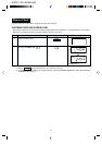
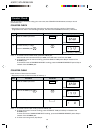
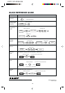
START
0 0
1
SELECT TIME
Please check the following before calling for service:
1.
When the door is opened, does the oven lamp and cooling fan come on for one minute?
YES _______ NO _______
2. Place one cup of water (approx. 250 ml) in a glass measure in the oven and close the door securely.
Programme the oven for 1 minute at 100%.
A. Does the oven lamp light? YES _______ NO _______
B. Does the cooling fan work? YES _______ NO _______
(Put your hand over the rear ventilation openings.)
C. After one minute, did an audible signal sound and heating
indicator "ON" go off? YES _______ NO _______
D. Is the water inside the oven hot? YES _______ NO _______
If “NO” is the answer to any of the above questions, please check your wall socket and the fuse in your meter box.
If both the wall socket and the fuse are functioning properly, CONTACT YOUR NEAREST SERVICE CENTRE
APPROVED BY SHARP.
AC Line Voltage: Single phase 230-240 V, 50 Hz
AC Power Required: 2.35 kW
Output Power: 1500 W *(IEC test procedure)
Microwave Frequency: 2450 MHz **(Class B/Group2)
Outside Dimensions: 510mm(W) x 335mm(H) x 470mm(D)(Single)
510mm(W) x 670mm(H) x 470mm(D)(Two oven stacked)
Cavity Dimensions: 330mm(W) x 180mm(H) x 330 mm(D)
Oven Capacity: 20 litre (0.7 cu.ft)
Cooking Uniformity: Stirrer fan system
Weight: Approx. 35 kg
* When tested in accordance with AS/NZS 2895.1.1995
** This is the classification of ISM(Industrial, Scientific and Medical) equipment described in the International
Standard CISPR 11.
SPECIFICATIONS
SERVICE CALL CHECK
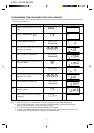
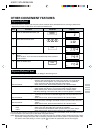
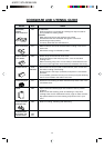
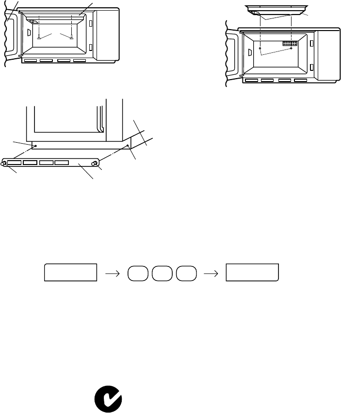
Splash cover:
AT LEAST ONCE A WEEK, REMOVE THE SPLASH COVER AND WASH BOTH SIDES OF IT IN A MILD
DETERGENT SOLUTION. A BUILD UP OF GREASE MAY OVERHEAT AND BEGIN TO SMOKE AND MAY BURN
THE SPLASH COVER. THE SPLASH COVER IS LOCATED IN THE TOP OF THE OVEN AND MAY EASILY BE
REMOVED. REMEMBER TO UNPLUG THE POWER CORD.
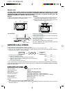
Removal:
1. Remove two thumb screws (A) as shown in Fig.1.
2. Remove the splash cover from the oven.
Reinstall:
1. Insert two projections of the cover (B) into the holes
of the oven cavity backplate as shown in Fig. 2.
2. Secure the cover to the oven ceiling with two
thumb screws (A) as shown in Fig. 1.
(A)
Door Splash cover
Fig. 1
(B)
Splash cover
Fig. 2
Holes
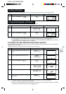
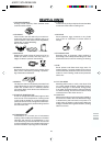
Keep the air intake filter clean. Clean the air intake filter
once every two weeks.
Remove the air intake filter by pulling the two (2) clips
on the sides of the filter.
Wash the air intake filter in mild soapy water, rinse and
dry with a soft cloth.
After cleaning re-install the air intake filter.
DO NOT OPERATE THE OVEN WITHOUT THE AIR
INTAKE FILTER IN PLACE.
Air intake filter:
Hole
Clip
Clip
Air intake filter
Oven
Hole