


3
A32727, SCA R2398 O/M
INSTALLATION INSTRUCTIONS
1. Remove all packing materials from the oven cavity. Remove the protective film(blue film) from the
outer case cabinet. Check the unit for any damage, such as a misaligned door, damaged door seals
around the door or dents inside the oven cavity or on the door. If there is any damage, please do not
operate the oven until it has been checked by a SERVICE CENTRE APPROVED BY SHARP and repaired,
if necessary.
2. Accessories provided
1) Operation manual and cooking
guide
2) Menu sticker
Enter cooking times or dish menus
in this sticker and attach to the
control panel.
3. The oven should not be installed in
any area where excessive heat and
steam are generated, for example,
next to a conventional oven unit.
The oven should be installed so as
not to block ventilation openings.
Allow at least 25 cm on the top, 5 cm
on the both sides and at the rear of the
oven for free air space.
4. Neither the manufacturer nor the dis-
tributors can accept any liability for
damage to the machine or personal
injury for failure to observe the cor-
rect electrical connecting procedure.
The A.C. voltage must be single
phase 230-240V, 50Hz.
5. It is recommended that a separate
circuit serving only this appliance be provided.
6. Operate the oven from a general purpose outlet.
If a generator is used, do not operate the oven with non-sinusoidal outputs.
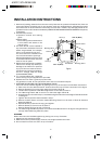
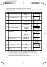
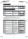
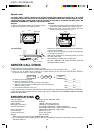
7. STACKING PROCEDURE FOR TWO MICROWAVE OVENS
Two units can be installed together by placing one on top of the other. Follow these instructions:
a. Place oven A in the desired location. Position Oven B on top of Oven A as shown in the figure.
b. Remove Screws (b) from the lower edge of the back of Oven B.
c. Loosen Screw (a) which holds Mounting Plate A on the back of Oven A.
d. Turn Mounting Plate A 180° so that it is on the lower edge of Oven B.
e. Using Screw (b) removed in step b, install Mounting Plate A to the lower edge of Oven B as shown
in the figure.
f. Tighten Screw (a) which was loosened in step c.
g. Remove another Screw (a) which holds Mounting Plate B on the back of Oven B. Remove
Mounting Plate B.
h. Replace Screw (a) removed in step g and tighten.
i. Remove Screw (c) from the rear of Oven A.
j. Remove Screw (d) from the rear of Oven B.
k. Turn Mounting Plate B and position it on Ovens A and B as shown in the figure. Using Screws (c)
and (d), fasten Mounting Plate B in place.
WARNING:
When two ovens are installed together by placing one on top of another:
1. Always use two mounting plates.
2. Make sure that the power supply cords are not caught between the ovens.
3. Do not install more the one oven on top of another.
Oven B (Back)
Rear cabinet
Mounting plate B
Screw (c)
Screw (a)
Screw (b)
Screw (a)
Oven A (Back)
Figure
Rear cabinet
Screw (d)
Mounting plate A