


7
Wartung
Bitte denken Sie daran, das Gerät bei jeder
Wartung vom Stromnetz abzuschalten.
Fettfilter
Der Fettfilter hat die Aufgabe, die im Koch-
dunst enthaltenen Fettpartikel aufzufangen.
Er befindet sich im Ansauggitter und ist in 4
Versionen lieferbar:
Der ca. 12-15 mm starke Kunstfaserfilter
wird bei normalem Gebrauch einmal im
Monat gereinigt und nach 5-6 Reinigungen
ausgewechselt.
Den Filter in lauwarmer Spülmittellauge aus-
waschen.
Der dünne, ca. 1 mm-starke Kunst-
faserfilter ist auszuwechseln, wenn der
obere Farbstreifen im unteren Teil erscheint.
Der dünne, ca. 1 mm-starke Kunst-
faserfilter ohne Sättigungsanzeige ist bei
normalem Gebrauch alle 2 Monate auszu-
wechseln.
Der Metallfilter hat eine fast unbegrenzte
Lebensdauer; so wie der Kunstfaserfilter ist
er einmal im Monat zu reinigen und darf erst
dann wieder eingesetzt werden, wenn er
vollkommen trocken ist.
Zum Entfernen des Filters M das Gitter öff-
nen, die Sperriegel L lösen, und ihn heraus-
ziehen. (Abb.5)
Wird der Fettfilter gereinigt, ist es empfeh-
lenswert, auch das Gitter in lauwarmer Spül-
mittellauge zu waschen.
Kohlefilter
Die Luft wird durch den Aktivkohlefilter
gereinigt und in den Raum zurückgeführt.
Bei normalem Gebrauch ist der Filter alle 4
Monate zu ersetzen.
Fordern Sie den neuen Filter beim
Kundendienst oder bei der Herstellerfirma
an.
Der Aktivkohlefilter ist keinesfalls waschbar.
Zum Auswechseln den Filter im Uhrzeiger-
sinn drehen, bis er aus seinem Sitz ausrastet.
Zur Beachtung
Die Nichtbeachtung der Reingungs-
vorschriften des Geräts sowie der Regeln
für die Auswechslung und Reinigung des
Filters kann zur Brandgefahr fuhren. Wir
empfehlen daher die folgenden Anweis-
ungen zu beachten.
Glühlampenwechsel
—Das Gerät vom Stromnetz abschalten.
—Das Gitter abheben.
—Die beschädigten Glühlampen auswech-
seln und olivenförmige 40 W-max.
Glühlampen (E14) verwenden.
—Falls der technische Kundendienst
angefordert werden soll, weil die
Beleuchtung nicht funktioniert, zuerst
überprüfen, ob die Glühlampen fest
eingeschraubt sind.
Reinigung
Für die äußere Reinigung der Haube einen
mit denaturiertem Alkohol oder neutralem
Flüssigreiniger Getränken Lappen ver-
wenden.
Der Gebrauch von scheuernden Produkten
ist zu vermeiden. Zur Reinigung der Teile
aus satiniertem Edelstahl sollte der Lappen
der Richtung der Satinierung entsprechend
gehalten werden.
Dieses Gerät entspricht den 87/308 EWG
Normen über Funkentstörung.
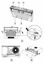
Hood description
1) Motor speed switch
2) Light switch
3) Removable drawer
4) Suction grid
5) Hob light
Opening the grid
—Move tabs E inwards (Fig.1).
—Pull the grid slightly outwards and turn it
downwards.
To remove the grid, slide it out from the right-
hand side until the grid is unhooked (Fig.2).
Removing the drawer-piece
— Push release button S and pull the front
panel door frontwards (release first by a
side, then by the other) (Fig. 1).
Fitting the removable drawer
— Fit the door snugly into guides R (Fig.3).
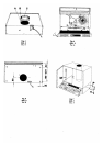
Use
Two systems are available:
— External exhaust system
— Internal recycle system
External exhaust system
Air is expelled by a duct which must be
connected to coupling ring C (Fig.4).
Lever G is positioned on setting "A" (Fig.5).
If the hood is provided with carbon filter,
it must be removed (fig. 2).
Internal recycle system (filtering)
Air is filtered through a carbon filter and then
pumped back into the room through the front
grid. This version is used when the room has
no external discharge pipe and it is not
possible to install one. In order to use this
version of the hood, proceed as follows:
— Turn lever G to setting "F" (Fig.2).
— If no filter is supplied with the hood, ask
the technical assistance service or
manufacturing company for one and
specify the hood model.
— To install the filter, insert it so that point E
matches up with arrow D (Fig.2) and turn
the arrow clockwise until it locks.
Installation
When installed. the hood must be not less
than 65 cm. above electric burners or 75 cm.
above gas or mixed-fuel burners.
In the vented exhaust version the fumes
outlet duct must be 100 mm. or 120 mm in
diameter according to the coupling ring
supplied. In the horizontal runs the duct
must be slightly slanted (about 10°) and
directed upwards to vent the air easily from
the room to the outside.
Electric connection
Before completing any connection, make
sure the house voltage corresponds with the
voltage indicated on the label affixed inside
the hood.
The hood is supplied with a standard plug;
connect it to a correspondingly standard
socket. In the case is intended to connect the
appliance permanently to the mains after
having removed the plug supplied, must be
fitted a two-pole switch conforming to
regulations with an opening distance
between contacts of not less than 3mm
The manufacturers are not liable for any
problems caused by the user’s failure to
observe the above instructions.
Fastening the removable drawer
Fasten the removable drawer N using the six
2.9x16 screws U supplied in the accessory
kit (Fig.1).
Remove the door to simplify this operation.
Fastening the hood to the wall
cupboard
Make a hole in the bottom of the cupboard as
shown in Fig.6 (do not consider the thickness
of the wooden panel).
In vented exhaust hoods, make a Ø115mm
hole (with pipes of Ø 100mm) or 135 mm
hole (with pipes of Ø 120mm), both on the
bottom and top of the cupboard for the
discharge pipe. From inside the cupboard,
insert the four 4,2x35 screws M supplied in
the accessory kit (Fig.7) and screw them to
the top of the hood.
If the cupboard is deeper than the hood ,
insert spacer P and fix it with 2 screws to the
back of the hood.
GB