


Instructions for the installer
22
2 POSITIONING OF THE HOB
The following operation requires building and/or carpentry work so must
be carried out by a competent tradesman.
Installation can be carried out on various materials such as masonry,
metal, solid wood or plastic laminated wood, as long as they are heat-
resistant (T 90°C).
2.1 Attachment to support structure, traditional built-i
n
model
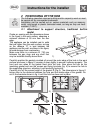
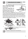
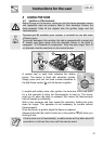
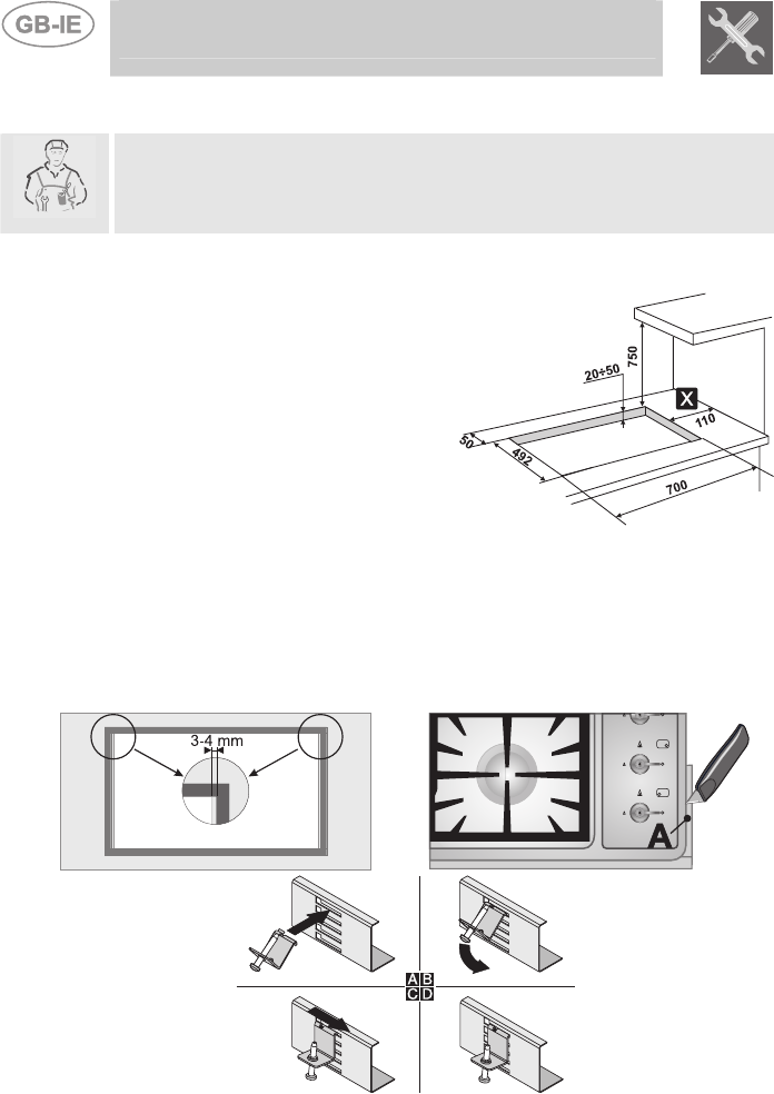
Create an opening with the dimensions shown
in the figure in the work surface, observing a
minimum distance of 50 mm from the rear
edge.
This appliance can be installed next to walls
that are higher than the work surface, as long
as the distance "X" is kept between the
appliance and the wall, as shown in the figure,
to avoid damage from overheating.
Make sure there is a minimum of 750 mm
between the gas rings and any shelf that
may be installed directly above them.
1)
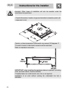
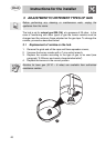
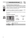
Carefully position the gasket provided all around the outer edge of the hole in the work
surface as shown in figure 2, pressing it down lightly to ensure it adheres properly. The
front and rear sides of the gasket must skim the hole. Now place the hob on the
insulating gasket and use the screws and fixing brackets (fig. 4) to secure the hob to
the supporting structure, adjusting it until perfectly horizontal.
Carefully trim off the excess edge of the gasket C (Fig.3). The dimensions in figure 2
below refer to the distance between the hole and the inside edge of the gasket. Do
not fit the brackets shown in fig. 4 until the hob has been set in place.
2) 3)
4)