


INSTALLATION
t
W-G: THESE PROCEDURES MUST BE FOLLOWED BY QUALIFIED
PERSONNEL OR WARRANTY WILL BE VOIDED.
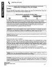
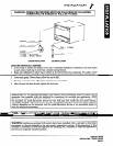
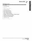
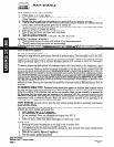
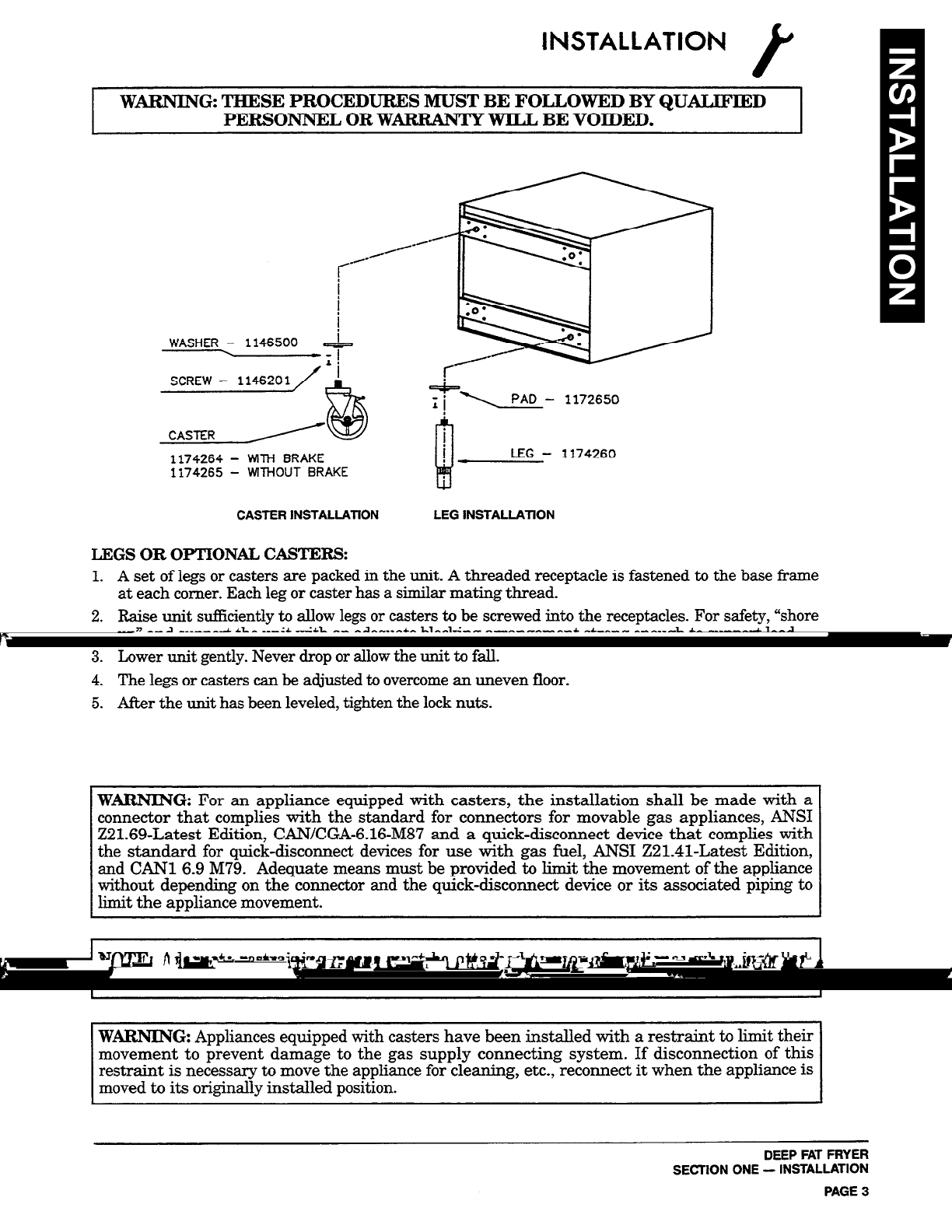
SCREW - 1146201
1174264 -
WlTH BRAKE
1174265 -
Wl-lHOUT BRAKE
j==, PAD -
1172650
i
B
i w
LEG -
1174260
CASTER INSTALLATION
LEG INSTALLATION
LEGS OR OPTIONAL CASTERS:
1. A set of legs or casters are packed in the unit. A threaded receptacle is fastened to the base frame
at each corner. Each leg or caster has a similar mating thread.
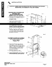
2. Raise unit sufhciently to allow legs or casters to be screwed into the receptacles. For safety, “shore
up” and support the unit with an adequate blocking arrangement strong enough to support load.
3. Lower unit gently. Never drop or allow the unit to fall.
4. The legs or casters can be adjusted to overcome an uneven floor.
5. After the unit has been leveled, tighten the lock nuts.
WARNING: For an appliance equipped with casters, the installation shall be made with a
connector that complies with the standard for connectors for movable gas appliances, ANSI
Z21.69-Latest Edition, CAN/CGA-6.16-M87 and a quick-disconnect device that complies with
the standard for quick-disconnect devices for use with gas fuel, ANSI ZBlRl-Latest Edition,
and CAN1 6.9 M79. Adequate means must be provided to limit the movement of the appliance
without depending on the connector and the quick-disconnect device or its associated piping to
limit the appliance movement.
NOTE: Adequate restraining means must be attached to rear of appliance when installed.
Installation must conform to local codes as applicable.
WARNING: Appliances equipped with casters have been installed with a restraint to limit their
movement to prevent damage to the gas supply connecting system. If disconnection of this
restraint is necessary to move the appliance for cleaning, etc., reconnect it when the appliance is
moved to its originally installed position.
DEEP FAT FRYER
SECTION ONE - INSTALLATION
PAGE 3