


INSTALLATION
B.
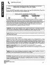
MODELS 1442,1436,18-42 and 18-36
INDIVIDUAL UNITS
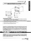
1. Remove valve panel.
2. Use a long spirit level four ways; across the front top rail and rear collar plate, and along
each edge.
3. (a) For units without a rear gas connection connect the gas supply to the right or
left side of the manifold. Be sure to cap the unused side.
(b) For units with a rear gas connection the supply to the unit will be made at the right
rear. Be certain both ends of the manifold are capped.
4. Turn off all burner valves.
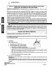
5. Turn on gas supply and immediately check all gas connections for leaks Use soapy water
only. NEVER use an open
flame.
6. Put valve panel back onto the unit.
7. Proceed to “MOUNTING SHELF OR BACKSPLASH INSTALLATION INSTRUC-
TIONS,” if applicable.
ASSEMBLY OF FRYERS AS PART OF A BATTERY:
1.
2.
3.
4.
5.
6.
7.
8.
9.
10.
11.
12.
Position the center range of the battery and carefully level unit. Use a long spirit level four ways;
across front top rail and the rear collar plate, and along each edge.
Remove all valve panels. Mark, so they will be returned to their respective unit.
Bring up adjacent unit, level by same method and by using the center unit as reference. Match
front rails and rear collar plates. When battery is set on a masonry base and legs are not used,
shims
may
be used. Special attention should be given to Fry Top ranges to allow proper drainage
on griddles.
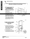
Where Spreader Plates are installed, refer to Sectional Battery Component Assembly Instruc-
tions supplied with each unit.
Connect units together by mating the unions. Make unions just HAND TIGHT at this
time.
Starting at the center and working toward the ends, tighten each union gradually, going from
one to another, until all are finally tight. A special thin wrench, which fits the union nut, is
provided with each battery or a chain wrench can be used.
Connect gas supply at right, left, or both ends. When a Spreader Plate with a “Tee” connection
is inserted in a battery, the gas supply may be connected at this point. Ranges with rear con-
nections may also be used in this respect. If five or more units are batteried, more than one
supply line should be used. Each supply line should have a readily accessible, approved hand
shutoff valve.
“Open” ends of the manifold must be capped.
Turn off all burner valves.
Turn on gas supply and immediately check all unions for leaks. USE SOAPY WATER
ONLY FOR TESTING ON ALL GASES. NEVER USE AN OPEN FLAME TO CHECK FOR GAS
LEAKS.
When entire gas system has been proved, turn off gas supply during additional installation.
A filler to cover the “gap” between the range fronts and tops is provided. Refer to Sectional
Battery Component Assembly Instructions supplied with each unit.
NOTE: Although the Fryers are equipped with an internal pressure regulator, other sectional ranges
to which they are batteried may require an external pressure regulator. This pressure regulator must
meet the following requirements:
1. The pressure regulator installed should be certified by a recognized testing agency.
2. The regulator should be acceptable for total pilot load application.
3. The regulator must have a maximum regulation capacity for the total connected load.
4. The regulator must have a pressure adjustment range to allow adjustment to the manifold
pressure on the appliance rating plate.
5. Unless the manifold pressure of all connected appliances is the same, a separate regulatcr must
be supplied for each unit(s) to indicate unit or units having differing manifold pressures.
DEEP FAT FRYER
SECTION ONE - INSTALLATION
PAGE 5