


\
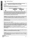
INSTALLATION
WARNING: THESE PROCEDURES MUST BE FOLLOWED BY QUALIFIED
PERSONNEL OR WARRANTY WILL BE VOfDED.
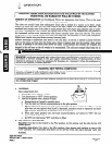
GAS CONNECTIONS:
The AGA. serial plate located on the back of the door (upper left corner> indicates the type of gas
your unit is equipped to burn.
Do Not connect
to any other gas type.
These models are design certified for operation on Natural
or
Propane gases.
The appliance should be connected ONLY to the type of gas for which it is equipped. All Southbend
equipment is adjusted at the factory, however, burner air shutters and pilot heights should be
checked at installation and adjusted if necessary. Check type of gas on serial plate on the inside of
the cabinet door.
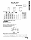
For orifice sizes and pressure regulator settings refer to the chart in “SERVICE” section.
If applicable, the vent line from the gas appliance pressure regulator shall be installed to the
outdoors in accordance with local codes or, in the absence of local codes, with the National Fuel Gas
Code, ANSI Z223.1-Latest Edition. Canadian installation must comply with CAN/CGA-B149.1
Natural Gas Installation Code, Code CAN/CGA-B149.2 Propane Installation Code.
An adequate gas supply is imperative. Undersized or low pressure lines restrict the volume of gas
necessary for satisfactory performance. A pressure regulator, which is provided with each unit, is set
to maintain a 4” W.C. manifold pressure for natural gas and a 10” W.C. manifold pressure for pro-
pane gas. However, to maintain these conditions the pressure on the supply line, when all units are
operating simultaneously, should not drop below 7” W.C. for natural gas or 11” W.C. for propane gas.
Purge the supply line to clean out any dust, dirt, or other foreign matter before connecting the line
to the unit. It is recommended that an individual manual shutoff valve be installed in the gas supply
line tc the unit. Use pipe joint compound which is suitable for use with LP gas on all threaded con-
nections. Test pipe connections thoroughly for gas leaks. USE SOAPY WATER ONLY FOR TESTING
ON ALL GASES. NEVER USE AN OPEN FLAME TO CHECK FOR GAS LEAKS. ALL CONNEC-
TIONS MUST BE CHECKED FOR LEAKS, AFTER THE UNIT HAS BEEN PUT IN OPERATION.
All pipe joints should be tested for leaks with a soap and water solution before operating the unit.
The test pressure should not exceed 14” W.C.
CAUTION:
THIS APPLIANCE AND ITS INDIVIDUAL SHUTOFF VALVE MUST BE
DISCONNECTED FROM THE GAS SUPPLY PIPING SYSTEM DURING ANY PRESSURE
TESTING OF THAT SYSTEM AT TEST PRESSURES IN EXCESS OF I/ 2 PSIG (3.45 kPa).
THIS APPLIANCE MUST BE ISOLATED FROM THE GAS SUPPLY PIPING SYSTEM BY
CLOSING ITS INDIVIDUAL MANUAL SHUTOFF VALVE DURING ANY PRESSURE
TESTING OF THE GAS SUPPLY PIPING SYSTEM AT TEST PRESSURES EQUAL TO OR
LESS THAN 1 I2 PSIG (3.45 kPa).
A 56” pressure tap is located on the combination gas control inside the cabinet and on the burner
manifold directly above the Unitrol.
I
CAUTION:
IF YOU SMELL GAS DURING THE LIGHTING PROCEDURE, IMMEDLATELY
SHUT OFF THE GAS SUPPLY UNTIL THE LEAKHAS BEEN CORRECTED.
1. All Fryers are factory shipped with a pressure regulator which is set for the type of gas denoted
on the serial plate.
2. On all threaded connections, the pipe joint compound must be approved for use with natural
and LP gas.
3. Check all connections thoroughly for gas leaks before lighting the pilot. Use soapy water only.
NEVER use a flame.
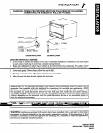
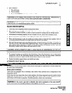
4. Gas connections are made as follows:
A. MODEL 14-32
1. Make gas supply connection directly to the ‘/i’ NPT (male) pipe protruding from the lower
left of the unit at the rear. When tightening the supply pipe be sure to hold the mating
pipe extending from the unit securely with a wrench. This will prevent any damage or
distortion to the internal piping and controls of the unit.
2. Use a long spirit level four ways; across the front top rail and rear collar plate, and along
each edge.
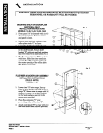
3. Proceed to “MOUNTING SHELF OR BACKSPLASH INSTALLATION INSTRUCTIONS”
(Model 14-32).
DEEP FAT FRYER
SECTION ONE - INSTALLATION
PAGE 4
Litho in U.S.A.
2-94