


MODEL 300 RESTAURANT RANGES INSTALLATION
Step 2b: Install Casters and Restraint
NOTICE
For an appliance equipped with casters, (1) the installation shall be made with a connector that
complies with the Standard for Connectors for Movable Gas Appliances, ANSI Z21.69 or Connectors
for Moveable Gas Appliances, CAN/CGA-6.16, and a quick-disconnect device that complies with the
Standard for Quick-Disconnect Devices for Use With Gas Fuel, ANSI Z21.41, or Quick Disconnect
Devices for Use with Gas Fuel, CAN1-6.9, (2) adequate means must be provided to limit the
movement of the appliance without depending on the connector and the quick-disconnect device or
its associated piping to limit the appliance movement and (3) the restraining means should be
attached to a frame member on the back of the unit.
INSTALLATION
A set of four casters is packed with units ordered with casters (instead of legs).
A threaded leg pad is fastened to the base frame at each corner. Each caster has a corresponding mating
thread. The casters can be adjusted to overcome a slightly uneven floor. Casters are provided with a Zerk
fitting for proper lubrication when required.
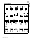
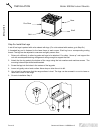
1. Raise unit sufficiently to allow leg pads and casters to be attached. For safety, “shore up” and support
the unit with an adequate blocking arrangement strong enough to support the load.
2. Attach the four leg pads to the bottom of the range using the lock washers and machine screws. The
mounting holes are pre-drilled and threaded.
3. Screw the casters into the holes in the centers of the leg pads. Install the casters that have a locking
brake under the front of the unit.
4. Lower unit gently onto a level surface. Never drop or allow the unit to fall.
5. Use a level to make sure that the range surface is level. The casters can be screwed in or out to lower or
raise each corner of the range. After the unit has been leveled, tighten the lock nuts.
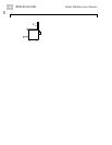
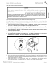
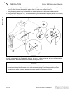
6. Secure the restraining-device bracket (item “B” in the following illustration) to a wall stud located as close
as possible to the appliance connector inlet and outlet connections. Use four #12 screws (items “C”) and
plastic anchors (items “A”) if necessary.
7. Install eye-bolt (item “F”) to a frame member on the rear of the equipment. After checking carefully
behind the frame member for adequate clearance, drill a 1/4" hole through the frame member.
OPERATOR’S MANUAL 1182298 REV 3 PAGE 11