GFS SERIES TUBE FRYERS SERVICE
OPERATOR’S MANUAL 1182026 REV 2PAGE 21
SERVICE
Checking and Adjusting Pressure Regulator
The combination gas valve and pressure regulator is factory set at 4" W.C. for natural gas and 10" W.C. for
propane gas. To check the manifold pressure, do the following:
1. Turn thermostat “OFF” (lowest position) and combination gas valve knob to the “PILOT” setting.
2. Remove pressure tap plug from burner manifold located directly below the burners in the cabinet.
3. Install a fitting appropriate to connect a manometer.
4. Turn combination gas valve to “ON” position and thermostat to “ON.” The burners will ignite. Be certain
that sufficient oil is covering the tubes.
5. With burners on, read manometer.
6. If the manometer does not read 4" W.C. for natural gas, or 10" W.C. for propane gas, adjust regulator.
7. Remove regulator adjustment screw cap (see diagram on page 24).
8. With small screwdriver rotate adjustment screw “CLOCKWISE” to increase or “COUNTERCLOCKWISE”
to decrease pressure. Be sure to adjust with burners “ON.”
9. Turn thermostat “OFF” and set combination gas valve knob to “PILOT” position.
10. Remove manometer and replace pressure tap plug.
11. Replace adjustment screw cap.
Checking and Adjusting Calibration of Thermostat
All thermostat controls are carefully calibrated at the factory (i.e., the dial is properly set to control appliance
temperatures accurately). Only a qualified appliance service technician should perform this adjustment.
1. To check appliance temperatures, use a thermocouple-type temperature test instrument or reliable
thermometer. Place the thermocouple of test instrument or thermometer in the center of the frypot.
2. Turn the control dial to the temperature setting requiring the greatest accuracy. Allow enough time for
temperature to stabilize, or until several temperature readings are identical.
3. Recalibrate if setting and actual temperature differ by more than 10°F.
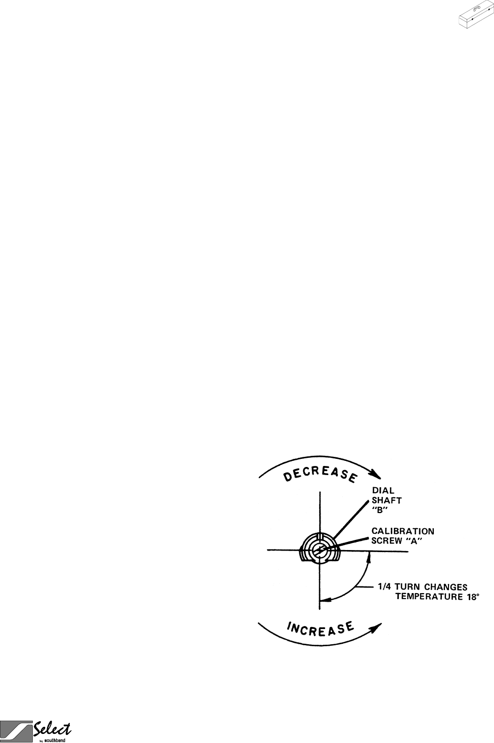
4. Remove dial from dial shaft “B.” Be careful that
dial shaft does not rotate in either direction
(which would change the dial setting).
5. Hold dial shaft “B” steady and with a screwdrive
turn calibration screw “A” clockwise to decrease
the temperature, or counterclockwise to increase
the temperature.
6. Replace dial. Let the appliance operate until the
temperature has stabilized before a final check is
made to determine whether or not the calibration
has been corrected.
7. Once correct, seal the calibration screw with
glyptol.


