


SERVICE INFRARED CHEESE MELTER
PAGE 20 OF 24 OWNER’S MANUAL 1186531 REV 2 (09/11)
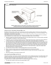
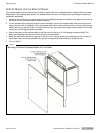
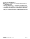
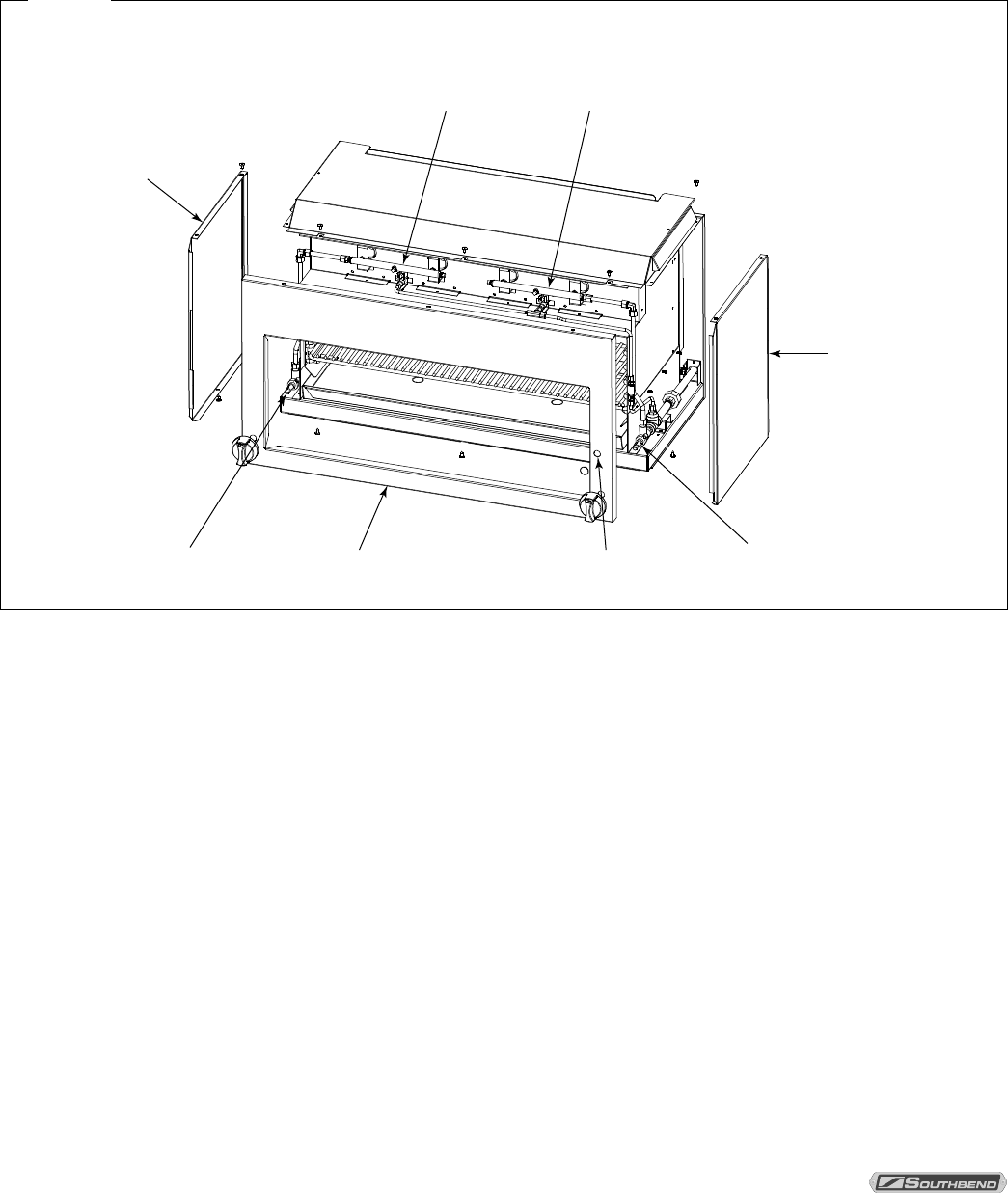
ACCESS TO SERVICEABLE PARTS
Some serviceable parts are only accessible by removing body side panels and the front panel.
The main front panel is fastened with six sheet-metal screws. To remove the front panel, remove these screws, as
well as the burner-control-valve knobs. The main front panel can then be pulled forward and removed. Each body side
panel is fastened with two sheet-metal screws. Remove body-side screws and slide the body side forward and away
from the unit.
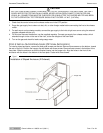
Figure 8
Access to Serviceable Parts
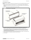
Body Side
Body Side
Left Pilot Right Pilot
Burner Valve Right
Burner Valve Left
Front Panel Dual-Pilot Adjustment-Screw Hole
If necessary (or convenient), wall-mounted and flue-riser-mounted models can be un-mounted for servicing or repairs.
Use two people since the cheese melter weighs as much as 265 pounds (120 kilograms). Refer to the installation
procedure in the previous section of this manual for guidance.
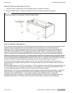
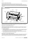
ADJUSTMENT OF CHEESE MELTER PILOTS
The pilots are adjusted at the factory. If later the pilots are over-adjusted to the point where the flame is leaving its
port, or “blowing off,” the result is an unstable condition in which the pilot may extinguish. If necessary, adjust the
pilots using the following procedure:
1. If necessary, light the pilots.
2. Locate the pilot adjustment screw (which adjusts both pilots). It is a small slotted screw located on the pilot valve,
and is accessed though the hole in the front panel above the right control-valve knob. On flame-failure option
units, the adjustment screw is located on the valve, and each pilot is adjusted separately.
3. Turn the pilot adjustment screw to adjust the size of the pilot flames. The flame on each pilot should be large
enough to extend along the flame carrier to the burner surface.
ADJUSTMENT OF CHEESE MELTER BURNERS
The infrared burners require no air adjustment after they have left the factory. If a major change in burner operation is
noticed, check for obstruction of airflow, around the orifice. Burner performance is affected by (a) orifice size, (b)
pressure, (c) injection, and (d) primary airflow. The burner orifice must be centered within the air mixer opening.