


SERVICE STRATOSTEAM COUNTERTOP STEAMER
TROUBLESHOOTING FLOWCHARTS, PROCEDURES, AND WIRING DIAGRAMS
Find the symptom below that corresponds to the malfunction, then turn to the corresponding page. Follow the
flowchart on that page until the problem is solved.
Troubleshooting Flowchart, Procedure, or Wiring Diagram Page
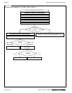
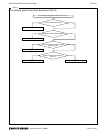
Troubleshooting Flowchart: Steamer Not Heating Up, “Power” Light Is Not Lit 24
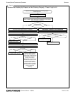
Troubleshooting Flowchart: Steamer Not Heating Up Properly or Not Cooking Properly, “Power” Light is Lit 25
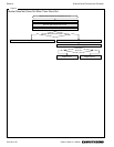
Troubleshooting Flowchart: Buzzer Does Not Come On When Timer Runs Out 26
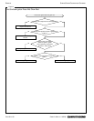
Troubleshooting Flowchart: Hot Surface Ignitor Glows Red, But Burners Not On 27
Troubleshooting Flowchart: Hot Surface Ignitor Does Not Glow Red 28
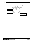
Troubleshooting Flowchart: Not All Burners Ignite 29
Troubleshooting Flowchart: Burner Lights But Goes Out Within a Few Seconds 30
Troubleshooting Procedure: Power Switch Check 32
Troubleshooting Procedure: Timer and Buzzer Check 33
Troubleshooting Procedure: Door Switch Check 34
Troubleshooting Procedure: High Limit Thermostats Check 35
Troubleshooting Procedure: Water Solenoid Check 36
Wiring Diagram for 208/220/240 Volt and 115 Volt Models 37
HOW THE STEAMER OPERATES
Compared to steam cookers that have complicated boilers, a StratoSteam steamer is a very simple machine. The
burners are integrated into the bottom plate of the cooking cavity, and begin to heat immediately as soon as the
steamer is turned on. As water flows into the cooking cavity it covers the heated bottom plate and is converted to
steam. There is no pressure in the steamer. From a cold start the steamer will heat up to cooking temperature in
about 4 minutes.
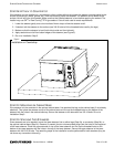
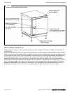
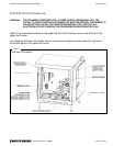
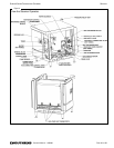
The internal components of the steamer are shown in Figure 10 on the next page.
Turning the control lever to ON mechanically actuates the power switch, and so turns on power to the rest of the
circuitry. The “Power” indicator light comes on. Turning the control lever to ON also mechanically closes the cooking-
cavity drain valve.
The gas ignition system is energized (turning on the gas valve) if (1) the door is shut (as sensed by the door switch),
and (2) the steamer is not overheated (as sensed by the high-limit thermostats).
The flow of water into the cooking cavity is controlled by the water solenoid, which is energized (turning on the water)
when the control lever is turned to ON and the door is shut. Hence, when cooking, water flows continuously into the
cooking cavity.
If a high-limit thermostat detects that the steamer is overheating, or detects low water (by sensing overheating), the
ignition switch is de-energized (turning off the gas valve). Overheating may be caused by too little water entering the
cavity, or by lime buildup inside the cavity reducing the conduction of heat to the water.
During operation, excess heated water flows into the drain box where it mixes with a small stream of cold water that is
continuously supplied to the drain box (to prevent the draining water from being too hot for the plumbing pipes). Water
drains from the drain box out the water drain on the rear of the steamer. If the drain is clogged, water backing-up into
the drain box will escape through the drain-box overflow vent on the rear of the steamer.
Any excess steam is vented out the pressure-relief valve located at the top left rear corner of the steamer.
The dial thermometer on the control panel is connected by a capillary tube to a sensor bulb located in the pressure-
relief vent. The thermometer does not affect the operation of the steamer.
A mechanical timer activates a buzzer when the timer times out. The timer does not affect anything else!
When the control valve is turned to OFF, power to the electric circuitry is turned off, which de-energizes the gas
ignition circuit and so shuts off the IR gas heaters. Turning the control lever to OFF also de-energizes the water
solenoid (turning off the water) and mechanically opens the drain valve, permitting all water to drain from the bottom
of the cooking cavity.
PAGE 22 OF 50 OWNER’S MANUAL 1185290