


GT18B01-B02 User Manual ◄ 3
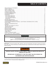
TABLE OF CONTENTS
WARNING
SERIOUS INJURY OR DEATH COULD RESULT FROM THE IMPROPER REPAIR OR
SERVICE OF THIS TOOL.
REPAIRS AND / OR SERVICE TO THIS TOOL MUST ONLY BE DONE BY AN
AUTHORIZED AND CERTIFIED DEALER.
SERVICING: This manual contains safety, operation, and routine maintenance instructions. Servicing of hydraulic
tools, other than routine maintenance, must be performed by an authorized and certied dealer. Please read the
following warning.
For the nearest authorized and certied dealer, call Stanley Hydraulic Tools at the number listed on the back of this
manual and ask for a Customer Service Representative.
IMPORTANT
To ll out a Product Warranty Recording form, and for information on your warranty,
visit Stanleyhydraulic.com and select the Warranty tab.
(NOTE: The warranty recording form must be submitted to validate the warranty).
DECLARATION OF CONFORMITY ....................................................................................................................... 2
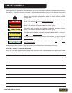
SAFETY SYMBOLS ...............................................................................................................................................4
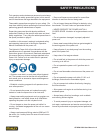
SAFETY PRECAUTIONS ......................................................................................................................................5
TOOL STICKERS & TAGS ..................................................................................................................................... 6
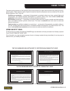
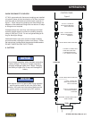
HYDRAULIC HOSE TYPES ...................................................................................................................................7
HOSE RECOMMENDATIONS ............................................................................................................................... 8
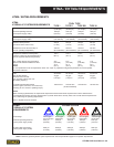
HTMA REQUIREMENTS .......................................................................................................................................9
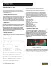
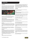
OPERATION ........................................................................................................................................................10
FOR 5 GPM OPERATION ..................................................................................................................................12
FOR 8 GPM OPERATION ..................................................................................................................................12
COLD WEATHER STARTUP .............................................................................................................................13
SHUTDOWN ......................................................................................................................................................13
ROUTINE MAINTENANCE .................................................................................................................................. 14
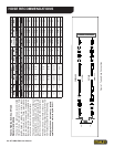
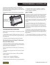
PROGRAMMABLE CONTROLLER ..................................................................................................................... 15
CHECKING PERFORMANCE CONTROL™ (ELECTRONIC GOVERNOR-STATIC CHECK) ...........................15
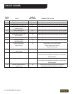
FAULT CODES .....................................................................................................................................................15
TESTING & TROUBLESHOOTING .....................................................................................................................17
GENERAL ............................................................................................................................................................17
TESTING THE HYDRAULIC CIRCUIT ................................................................................................................17
TROUBLESHOOTING .........................................................................................................................................18
SPECIFICATIONS ................................................................................................................................................19
BRIGGS ENGINE ASSEMBLY .............................................................................................................................20
BRIGGS ENGINE PARTS LIST ...........................................................................................................................21
FUEL TANK & CAP ..............................................................................................................................................22
FRAME PARTS ....................................................................................................................................................23
HOSES, FITTINGS & CLAMPS ...........................................................................................................................24
MAIN POWER UNIT WIRING HARNESS ............................................................................................................25