


10 ► IP16 User Manual
NOTE:
High-pressure couplings must be used for the high-
pressure connections at the output side of the in-
tensier.
4. Connect the tool to be used (stretcher, cutter, etc,)
to the unit. Refer to the applicable Operation Manual
for detailed connection procedures.
5. Move the hydraulic circuit control valve to the ON
position to operate the intensier.
NOTE:
If uncoupled hoses are left in the sun, pressure in-
crease within the hoses may make them difcult to
connect. When possible, connect the free ends of
operating hoses together.
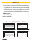
TOOL OPERATION
1. Observe all safety precautions
2. Activate the parent circuit to energize the intensier.
Pressure should now be available at the pressure
port of the tool. At this time, the control valve and
tool are ready for operation.
3. Verify operating pressure requirements of tool being
used and adjust intensier relief valve as required.
NOTE:
Higher ows and/or high back-pressure will in-
crease the output pressure. Adjust the output relief
valve under the ow and operating conditions the
tool will be used under.
The load valve locks the tool outlet and is to be used
to hold the tool in a xed position. The pressure gauge
reads on the tool side of the valve to monitor the load.
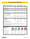
COLD WEATHER OPERATION
If the tool is to be used during cold weather, preheat the
hydraulic uid at low engine speed. When using the nor-
mally recommended uids, uid temperature should be
at or above 50 °F/10 °C (400 ssu/82 centistokes) before
use.
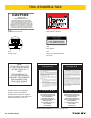
PRE-OPERATION PROCEDURES
FILL RESERVOIR
1.
IMPORTANT
Mil-H 5606 Hydraulic Oil must not be used in the
reservoir of the intensier.
Remove the vent plug from the top of the intensier.
Fill with clean hydraulic oil ltered to 10 microns or
less. Fill to top of high pressure pump as viewed
from the ller hole.
2.
IMPORTANT
Do not ll to top of hole. An air space is required for
hydraulic oil expansion as oil temperature increases.
An over-full reservoir will cause oil leakage from the
vent plug as the oil heats. If this condition occurs,
remove the vent plug and lower oil level to the point
specied.
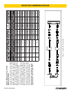
CHECK HYDRAULIC POWER SOURCE
1. Using a calibrated owmeter and pressure gauge,
check that the hydraulic power source develops a
ow of 4–10 gpm/15–38 lpm at 1000–2000 psi/70–
140 bar.
2. Make certain the hydraulic power source is equipped
with a relief valve set to open at 2100–2300 psi/145–
159 bar maximum.
3. Check that the hydraulic circuit matches the tool for
open-center (OC) operation.
CONNECT HOSES
1. Remove the thread protectors and valve caps from
the intensier.
2. Wipe all hose couplers with a clean lint-free cloth
before making hose connections.
3. Connect hydraulic lines from the parent circuit to the
intensier inlet tting. Make certain the “P” (pres-
sure) and “T” (tank) hoses are connected to their
respective ports. If incorrectly connected, high pres-
sure output will not be obtained.
OPERATION