


subzero.com
|
17
MODEL 427G / 427RG INSTALLATION
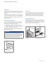
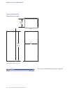
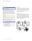
KICKPLATE INSTALLATION
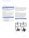
Install the kickplate using the screws provided. The
mounting bracket may be adjusted slightly for a ush t. The
kickplate must be removable for service. The oor cannot
interfere with removal. Refer to the illustration below.
A decorative kickplate can be added to the factory-installed
kickplate but cannot block the kickplate louvers.
Turn power on by touching POWER on the control panel.
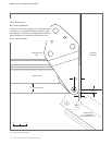
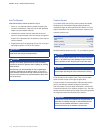
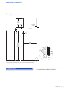
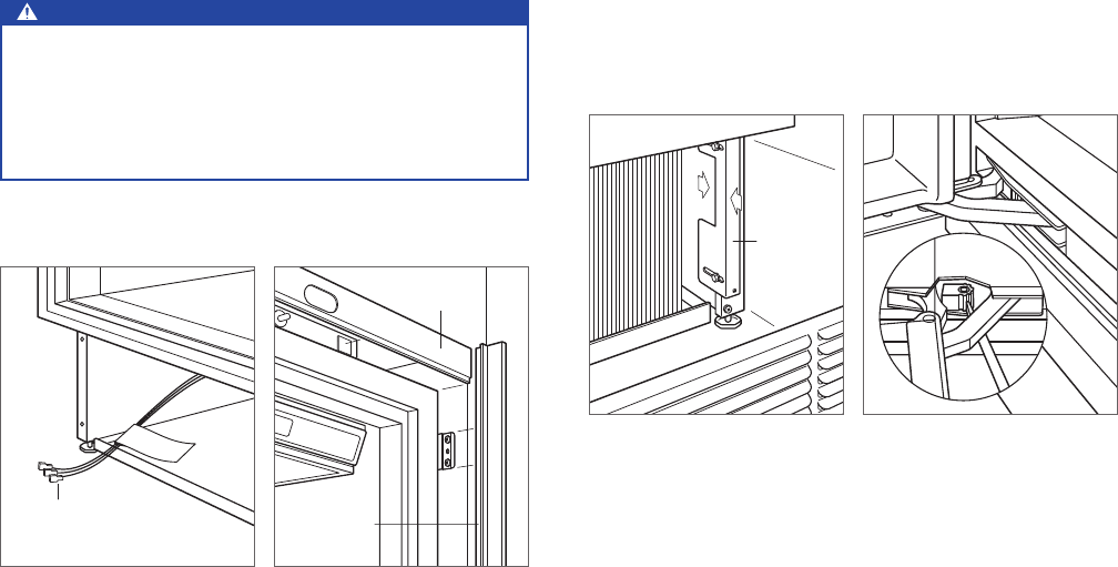
90° DOOR STOP
The door opens to 105°. A 90° door stop is built into the
hinge system for installations where the door opening must
be limited.
To engage the door stop, use a standard screwdriver and
rotate the center cam of the hinge. The adjustment must be
made to both upper and lower hinges. Refer to the illustra-
tion below.
MOUNTING
BRACKET
Kickplate installation.
90° door stop.
Completion
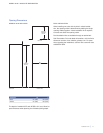
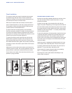
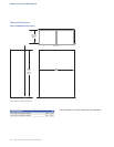
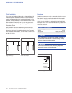
TRIM INSTALLATION
Install decorative trim strips to the top and sides of the unit.
Attach the top trim using the double-sided velcro, then snap
side trim over brackets on the sides of the unit. Refer to the
illustration below.
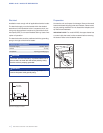
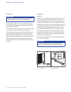
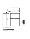
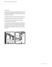
HOME SECURITY CONNECTION
If the unit will be connected to a home security system,
make connections to the leads shown in the illustration
below. Refer to the following color codes:
• Normally open contacts—white with red stripe wire.
• Normally closed contacts—white with blue stripe wire.
• Common—gray with white stripe wire.
Use the spade terminals or wire nuts provided to make
proper wiring connections.
CAUTION
The alarm circuit in the unit is intended as a low-
voltage, low-current device only. It should not be used
to switch line power. Any unused terminals should be
completely insulated and all wires should be secured
away from conductive or moving components.
HOME SECURITY
LEADS
TOP TRIM
SIDE TRIM
Home security connection.
Trim installation.