


7
Dimensions in parentheses are in
millimeters unless otherwise specified.
I NS TA LL AT IO N I N S T R U C T I O N S
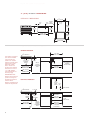
3 0" ( 76 2) D R A W E R MI CR OWAVE
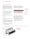
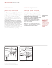
O V E R A L L D I M E N S I O N S
I N S TA L L AT I O N S P E C I F I C AT I O N S
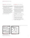
Standard Installation
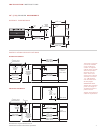
Flush Inset Installation
28
7
/16" (722)
OPENING WIDTH
23
1
/2"min(597)
OPENING DEPTH
33" r
ec (838)
30"m
in (762)
C
ABINET WIDTH
36" (
914)
STANDARD
FLOOR TO
COUNTERTOP
HEIGHT
E
5"
(127)
4"
(
102)
A
LLOW FOR
UP TO
3
/4" (19)
O
VERLAP
O
N ALL SIDES
2" (51)
24" min (610)
CABINET DEPTH
3
1
/2"(89) x 2"(51)
ANTI-TIP BLOCK
14
3
/4" (375)
O
PENING
H
EIGHT
36" rec (914)
33"min (838)
CABINET WIDTH
30
3
/8" (772)
FLUSH INSET WIDTH
28
1
/2" (724)
OPENING WIDTH
E
1"(25)
SIDE CLEATS
11
/16"(17) PLATFORM
7
/16"(11)TOP CLEAT
TOP VIEW
SIDE CLEATS
24
3
/4"min
(629)
FLUSH
INSET
DEPTH
1
1
/4"
(32)
36" (914)
STANDARD
FLOOR TO
COUNTERTOP
HEIGHT
1
9
/16" (38)
25"min (635)
CABINET DEPTH
14
3
/4" (375)
OPENING
HEIGHT
15
15
/16"
(405)
FLUSH INSET
HEIGHT
3
1
/2"(89) x 2"(51)
ANTI-TIP BLOCK
2
3
3
/8" (594)
BEHIND FRAME
1
5
7
/16"
(
392)
2
9
7
/8" (
759)
2
8
1
/8" (
714)
POWER
CORD
C
HANNEL
1
1
/4"
(32)
4
11
/16"
(119)
2"
(51)
14
9
/16"
(
370)
2
3
3
/8"
(
594)
16
1
/2"
(419)
29
7
/8" (759)
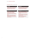
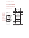
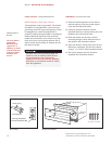
The drawer microwave
can also be installed
using an electrical
outlet in an adjacent
cabinet within the area
where the provided
electrical cord can
reach. Power cord
access hole in cabinet
should be a minimum
1
1
/2" (38) diameter
hole and deburred of
all sharp edges.
IMPORTANT NOTE:
Always allow sufficient
power cord length to
the electrical outlet to
prevent tension.
Always check electrical
codes for requirements.