19
PANEL INSTALLATION
If you have questions, contact your Sub-Zero
dealer or cabinet supplier. Additional panel
information can be found in the Sub-Zero
Design Guide.
DOOR PANEL INSTALLATION
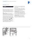
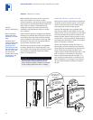
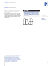
Remove the two pieces of mounting hardware
attached to the front of the door and set aside.
Place the door panel lying face down on a
protected surface to ensure that the front is not
scratched or damaged.
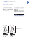
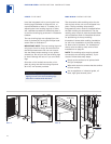
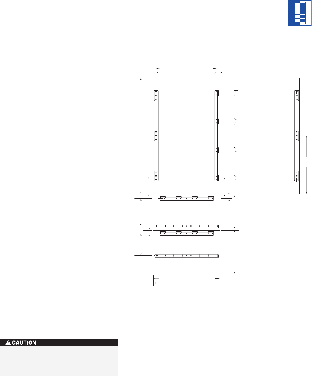
Position the plastic template provided flush
with the lower edge of the door. Be sure you
are following the exact location for the right-
hand (RH) or left-hand (LH) door position.
Refer to illustration 12 on page 18.
IMPORTANT NOTE:
The template has two
usable sides, one side for the door and one for
the drawers. Make sure you use the proper
holes and side. Remember you are viewing the
door panel from the back side in illustration 12
on page 18.
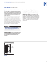
Once you have located the proper position for
the bracket, mark the pilot holes, remove the
template and drill pilot holes for mounting the
bracket. It is best to start with a few holes,
position the bracket, drill the remaining pilot
holes and then secure the mounting bracket
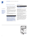
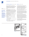
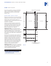
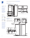
with the #8 x 12,7 mm screws provided. Illus-
tration 13 shows the mounting hardware
location for door and drawer panels.
IMPORTANT NOTE:
Dimensions in illustration
13 are based on a 3 mm reveal. A reveal of up
to 6 mm is possible, but panel dimensions
need to be adjusted accordingly.
INTEGRATED INSTALLATION INSTRUCTIONS
1153
mm*
345
mm
424
mm*
132
mm
135
mm
214
mm
287
mm
32
mm
32
mm
570
mm
679 mm*
FOR 686 mm WIDE UNITS
908 mm* FOR 914 mm WIDE UNITS
606 mm* FOR 686 mm WIDE UNITS
835 mm* FOR 914 mm WIDE UNITS
VIEW FROM BACK OF PANELS
*DIMENSIONS MAY VARY
PANEL BRACKET POSITIONING
LH DOOR SWINGRH DOOR SWING
37 mm*
Exercise caution when drilling holes for
mounting hardware. This is especially
critical with inset panels.
Illus. 13


