


10
INTEGRATED INSTALLATION SPECIFICATIONS
PLUMBING REQUIREMENTS
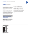
For Integrated models with an automatic ice
maker, rough in the water supply line. Connect
the 6,35 mm water line from the ice maker
water valve to the copper water supply. Use an
easily accessible shut-off valve between the
water supply and the unit. This shut-off valve
should not be installed behind the unit. Do not
use self-piercing valves. A saddle valve kit
(part #4200880) is avail able from your Sub-
Zero dealer.
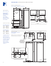
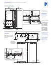
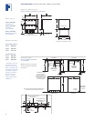
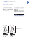
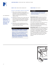
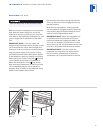
The Installation illustrations on pages 6–8
show the precise placement of the water line.
When routing through the side walls, you must
place the water line within 13 mm of the floor
and as close as possible to the back wall.
The line must be routed around the anti-tip
bracket so it clears the bracket and the leveling
feet of the unit. Refer to the top view in the
Installation illustration for your unit on pages
6–8. Regardless of the routing, allow for 686
mm of excess water line to remain outside the
wall or floor for easy connection to the unit.
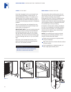
IMPORTANT NOTE:
Do not route the water
supply line in front of the compressor tray.
The tray must be slid forward for service.
A line filter is required when water conditions
have a high sediment content. The ice maker
operates on water pressure of 1.4 bar to
6.9 bar.
A reverse osmosis system can be used,
provided there is a consistent water pressure
of 1.4 bar to 6.9 bar supplied to the water valve
at all times.
IMPORTANT NOTE:
In some cases a reverse
osmosis water filter system may not be able
to maintain the minimum water pressure
consistently.
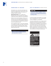
ACCESSORIES
Optional acces-
sories are available
through your
Sub-Zero dealer. To
obtain local dealer
information, visit
our website,
subzero.com.