


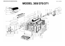


4 Models 369/370/371
1 TECHNICAL CHARACTERISTICS
The electric diagram of the dispenser is located inside
inner part of the dispensing side panel.
Specifications are subject to change without notice.
2 INTRODUCTION
Please read all sections of this manual thoroughly to familiarize
yourself with all aspects of the unit.
Like all mechanical products, this machine will require cleaning
and maintenance. Dispenser operation can be compromised
by operator’s mistakes during disassembly and cleaning. It is
strongly recommended that personnel responsible for the
equipment’s daily operations, disassembly, cleaning, sanitizing
and assembly, go through these procedures in order to be
properly trained and to make sure that no misunderstandings
exist.
3 INSTALLATION
1 - Remove the corrugated container and packing materials
and keep them for possible future use.
2 - Inspect the uncrated unit for any possible damage. If
damage is found, call the delivering carrier immediately to
file a claim.
3 - Install the unit on a counter top that will support the
combined weight of dispenser and product bearing in
mind what is stated in the preceding point 1
IMPORTANT warning.
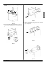
4 - A minimum of 15 cm (6”) of free air space all around the
unit should be allowed to guarantee adequate ventilation.
5 - Ensure that the legs are screwed tightly into the base of
the machine.
Replace the standard legs originally installed with the 100
mm (4”) legs whenever they are provided with the unit.
6 - Before plugging the unit in, check if the voltage is the same
as that indicated on the data plate. Plug the unit into a
grounded, protected single phase electrical supply
according to the applicable electrical codes and the
specifications of your machine. When the unit has no plug,
install a proper grounded plug, in compliance with
electrical codes in force in your area, suitable to at least
10 Amp 250 Volt (220-230 Volts 50-60 Hz areas) and
20 Amp 250 Volt (100-115 Volts 50-60 Hz areas)
applications. Should you prefer to connect the unit directly
to the mains, connect the supply cord to a 2-pole wall
breaker, whose contact opening is at least 3 mm (0.12”).
Do not use extension cords.
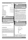
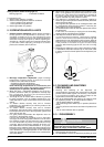
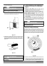
7 - Each drip tray has two diaphragm plugs: if a continuous
drain is needed, perforate one of the drain plugs and
connect it to a flexible drain line (see figure 1).
figure 1
8 - The unit doesn’t come presanitized from the factory.
Before serving products, the dispenser must be
disassembled, cleaned and sanitized. according to this
handbook instructions (chapter
5.3 CLEANING AND SANITIZING PROCEDURES).
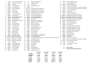
Transparent removable bowls n 1 2 3
Capacity of each bowl, approx. l 10 10 10
Dimensions:
width cm 28 36 54
width inch 11 14 21
depth cm 47 47 47
depth inch 19 19 19
height cm 69 69 69
height inch 27 27 27
Net weight, approx. kg 26 37 49
Net weight, approx. lb 57 82 108
Gross weight, approx. kg 29 40 54
Gross weight, approx. lb 64 89 119
Adjustable thermostats n 1 2 3
Hermetic compressor
Air-cooled condenser
Overload protector
Safety pressure switch
Noise level lower than 70 dB (A)
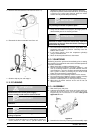
IMPORTANT
Read electrical ratings written on the data plate of the
individual units. The data plate is adhered on the
dispensing side panel of the unit, just behind the drip
tray (the right side drip tray in multiple bowl models).
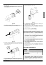
The serial number of the unit (preceded by the
symbol #) is adhered inside the left switch box. Data
plate specifications will always supersede the
information in this manual.
IMPORTANT
When handling the machine never grasp it by the bowls
or by the evaporator cylinders. The manufacturer
refuses all responsibilities for possible damages which
may occur from incorrect handling.
ATTENTION
Failure to provide proper electrical ground according to
applicable electrical codes could result in serious shock
hazard.
369P
370
371