STEP 1
PLAN THE INSTALLATION
Carefully follow the planning procedures listed below.
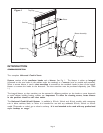
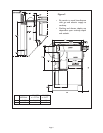
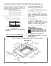
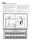
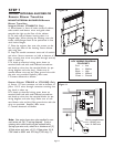
See Figure 2.
A. Determine whether a remote or integral blower will
be used. Remote blower installation requires 5
wires plus a ground wire to run from the
Cook‘n’Vent
®
to the blower.
B. Make sure adequate cabinet and counter space has
been provided for unit service if required.
C. Minimize cross drafts created by adjacent open win-
dows, doors, air conditioning, old heating vents,
recessed ceiling lights, and traffic patterns which may
affect performance.
D. For gas cooktop installations make sure that a mini-
mum 10 square inch opening is provided in the toe-
kick or other cabinet area. Inadequate ventilation of
the cabinet below the cooktop may result in flame
outage when operating the vent system.
E. Provide "make-up air" to installation location to
improve performance and prevent problems, such as
fireplace chimney downdrafts.
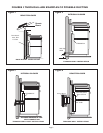
F . Investigate potential ductwork routes and choose
the shortest possible route from the unit to an
outside wall or roof. For guidance, typical ducting
installations are shown in figures 3 through 6.
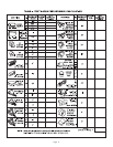
G. Determine whether the chosen route of ducting
will meet vent system performance require-
ments. To do this, measure the duct lengths
needed and determine specific fittings required.
Enter this data in the spaces provided in Table 1.
H. Follow the duct installation guidelines in Table 2.
Page 3
PARTS INCLUDED:
PARTS NEEDED:
• Small flat head screwdriver
• Small phillips head screwdriver
Parts Needed for Remote Blower:
• 5 min. 18 AWG, max 14 AWG wires and
1 ground wire.
• 1-1/2" box connector
• (3-1/4" x 14") to a 10" Diam. duct
transition for VTR1000R Remote Blower
• (3-1/4" x 14") to a 8" Diam. duct
transition for VTR600R Remote Blower
Parts Needed for Integral Blower:
• 6"-8" Duct Transition for Integral
VTN600CVA Blower
• #8, 1" phillips head wood screws (4 ea.)
• wire nut (spring type wire nuts, rated
for a min. of (2 #18 AWG wires, UL
and CSA rated to 600V and 302 deg.F/
150 deg. C)


