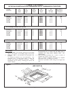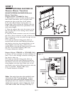
TABLE 2. DUCT WORK INSTALLATION GUIDELINES
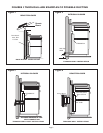
• Keep duct runs as short and straight as possible.
• Duct fittings (elbows and transitions) reduce air
flow efficiency.
• Back to back elbows and "S" turns significantly
reduces air flow and are not recommended.
• A short straight length of duct at the inlet of the
remote blower gives the best delivery.
• Transition to round duct as close to the
Cook‘n’Vent® as possible. In order of preference,
use
1st. 10" round duct
2nd. 8" round duct
3rd. 7" round duct
4th. 3-1/4" x 14" duct
5th. 3-1/4" x l0" duct
6th. 6" round duct
• The use of flexible metal round duct should only
be used when no other duct fitting exists. Limit use
to short lengths and do not crush when making
corners.
• Where local codes permit, plastic pipe (PVC-
schedule 40 pipe or ABS pipe 7" or 8" diameter) can
be used in areas of high ground moisture and in slab
floors to eliminate future rusting.
• Use only duct work constructed of materials that
are acceptable by the applicable codes. All duct should
be 26 gauge or heavier to minimize flex due to air flow.
• If the VTR1000Q is used, then a 10" diam. round
duct to match the inlet ring is required or a transition
to a 10" diam. is necessary from other duct sizes.
• If the VTR600R is used, then a 8" diam. round duct
to match the inlet ring is required or a transition to a
8" diam. is necessary from other duct sizes.
• Use sheet metal screws as required to support the
duct weight, and seal all joints with duct tape.
• Be certain that the duct work does not interfere
with floor joists or wall studs.
• Do not exhaust more than one vent into a single
duct run.
• Thermal breaks, such as a short section of
nonmetallic duct, should be used in areas of extreme
cold.
• Always use an appropriate roof or wall-cap with
damper. Laundry type wall caps should
never be
used.
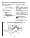
For installation of the Cook'n'Vent
®
with a Thermador
cooktop, refer to Part A and Figure 7. For installation
with another brand of cooktop, refer to Part B and
Figure 8.
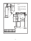
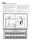
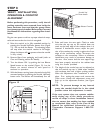
For all installations, verify cutouts will clear the inside of
the front countertop support rail. (See cutout depth in
Figure 2). The front and rear cutouts must be straight
and parallel to the front edge of countertop and the
rear backsplash or wall. Assure that the side cutouts
are square to the front and rear cutouts. All illustrations
and dimensions are based upon standard 24" deep by
36" high American style base cabinets with 25"
countertops.
When installing laminated or solid surface countertops
STEP 2
PREPARE COUNTERTOP CUTOUT
such as Surell™ and Corian
®
,
be sure to follow the
countertop manufacturer's instructions regarding mini-
mum corner radii, reinforcement of corners, etc.
For overhead cabinet and cooktop side clearances
consult cooktop Installation Instructions.
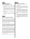
A. INSTALLATION WITH A
THERMADOR COOKTOP
(FIGURE 7 AND TABLE 3)
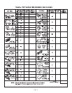
Provide an opening in the countertop as specified in
Table 3. Make sure the distance from the front of the
countertop to the front of the cutout is not less than
dimension "SB." Verify that the available flat countertop
is greater than dimensions "OW" by "OD." Make
certain the backsplash thickness does not exceed
dimension "BT".
Page 7


