


The stainless steel surfaces may be cleaned by
wiping with a damp soapy cloth. Any mild glass
cleaner will remove fingerprints and smears.
Follow all cleaning by rinsing with clear water. Wipe
dry with a clean soft cloth to avoid water marks. For
discolorations or deposits that persist, use a non-
scratching household cleanser or stainless steel
polishing powder with a little water and a soft cloth.
For stubborn cases, use a plastic scouring pad or
soft bristle brush together with cleanser and water.
Rub lightly in direction of polishing lines or "grain"
of the stainless finish. Avoid using too much pres-
sure which may mar the surface.
Use a stainless steel cleaner/polish to protect the
finish and maintain appearance.
DO NOT allow deposits to remain for long periods
of time.
DO NOT use ordinary steel wool or steel brushes.
Small bits of steel may adhere to the surface
causing rust.
DO NOT allow salt solutions, disinfectants, bleaches
or cleaning compounds to remain in contact with
stainless steel for extended periods. Many of these
compounds contain chemicals which could prove
harmful. Rinse with water after exposure and wipe
dry with a clean cloth.
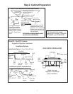
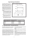
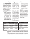
LOW BACK AND ISLAND TRIM MODEL NUMBERS
COOKTOP MODEL NO. 12" LOW BACK Island Trim*
P24WK GP24LBS GP24ITS
PC36 GPS36LBS GPS36ITS
PC48 GPS48LBS GPS48ITS
*Requires a minimum of 12" horizontal clearance between back of appliance and combustible materials.
TO CLEAN AND PROTECT EXTERIOR SURFACES
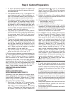
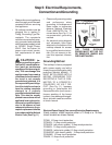
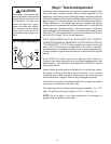
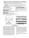
Step 6: Backguard Installation
A Low Back backguard must be in-
stalled when there is less than a 12"
clearance between combustibles and
back edge of cooktop. (See Fig. 1 and
5.) For island installations and other
installations with over 12" clearance, an
optional stainless steel trim channel is
available to cover the backguard mount-
ing flanges. Attach the backguard be-
fore sliding the appliance into the final
installed position. Follow Steps A through
C below:
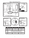
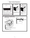
A. Slide backguard over the two flanges
on the rear of the appliance. Fasten
the front and back with two screws
(see A, Fig. 12) provided. No screws
are required behind the griddle sec-
tion.
B. Fasten the top of the backguard to
the wall with two screws through the
backguard. (See B, Fig. 12.)
C. Place the backguard cap on top and
fasten using the two counter-sink
screws provided. (See C, Fig. 12.)
FIG. 12 Low Back Attachment
C
B
A
12